Thursday, 22 October 2015

Latest Electronics Projects and Circuits

  • RFID Based Attendance System Project using 8051 Microcontroller
    In this RFID based Attendance System project, we will explain you how can we count attendance automatically by using RFID cards. RFID Tecnology (Radio Frequency Identification and Detection) is commonly used in schools, colleges, office and stations for various purposes to automatically keep a track of people.  Here we will count the attendance of an authorised person by using RFID.
  • Fire Alarm System using AVR Microcontroller
    In this project, we are going to make a Fire Alert System using ATMEGA8 microcontroller and fire sensor. Fire sensor can be of any type, however we are using IR (Infrared) based Fire Sensor. Although IR based Fire Sensors have some disadvantages mostly of inaccuracy, it is the cheapest and easiest way to detect fire.
  • Digital Code Lock using Arduino
    Security is a major concern in our day to day life, and digital locks have became an important part of these security systems. One such digital code lock is imitated in this project using arduino board and a matrix keypad. 
  • Remote Controlled Light Switch
    IR LED emits infrared light, and used in TV remotes. This Infrared is received by the receiver TSOP17XX (TSOP 1738used in TV). TSOP17XX receives the modulated Infrared waves and changes its output. TSOP is available in many frequency ranges like TSOP1730, TSOP1738, TSOP1740 etc. Last two digits represent the frequency (in Khz) of modulated IR rays, on which TSOP responds. Like for example TSOP1738 reacts when it receives the IR radiation modulated at 38Khz. TSOP output is active low, means it becomes LOW when IR is detected.
  • Color Detector using Arduino
    In this project we are going to interface TCS320 color sensor with Arduino UNO. TCS320 is a color sensor which can detect any number of colors with right programming. TCS230 contains RGB (Red Green Blue) arrays. As shown in figure on microscopic level one can see the square boxes inside the eye on sensor. These square boxes are arrays of RGB matrix. Each of these boxes contain Three sensors, One is for sensing RED light intensity, One is for sensing GREEN light intensity and the last in for sensing BLUE light intensity.
  • Arduino Alarm Clock
    This Arduino based Real time clock is a digital clock to display real time using a RTC IC DS1307which works on I2C protocol. Real time clock means it runs even after power failure. When power is reconnected, it displays the real time inrespective to the time and duration it was in off state. In this project we have used a 16x2 LCD module to display the time in - (hour, minute, seconds, date, month and year) format.
  • Light Intensity Measurement using LDR and ATmega8 Microcontroller
    In this project we are going to interface LDR with ATMEGA8 microcontroller, and with this we can measure LIGHT INTENSITY in the area. In ATMEGA8, we are going to use 10bit ADC (Analog to Digital Conversion) feature to measure the light intensity.
  • Digital Ammeter using AVR Microcontroller
    In this project we are going to make a low range ammeter using ATMEGA8 microcontroller. In ATMEGA8, we are going use 10bit ADC (Analog to Digital Conversion) feature to do this. Although we have few other ways to get the current parameter from a circuit, we are going to use resistive drop method, because it’s the easiest and simplest way to get current parameter.
  • UART Communication Between Two ATmega8 Microcontrollers
    In this tutorial we are going to establish a serial communication between two ATMEGA8 microcontrollers. The communication established here is UART (Universal Asynchronous Receiver Transmitter) type. By this serial communication data can be shared between two microcontrollers, which is required in various embedded systems.
  • Line Follower Robot using 8051 Microcontroller
    Line follower Robot is a machine which follows a line, it may be a black line or a white line. Basically two types of line follower robots are: one is black line follower which follows black line and second one is white line follower which follows white line. Line follower actually senses the line and run over it. In our previous projects, we have made a black line follower robot using arduino but this time we are going to make white line follower using 8051 microcontroller. In this tutorial, we will also cover how to make a printed circuit board for line follower robot at home in low price. 
Check more interesting projects and circuits here: Electronics Projects

Wednesday, 7 October 2015

DIY RGB Bulb


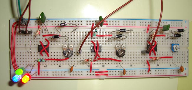
We are building here a RGB bulb using Red, Green and Blue LEDs, we just need to add a mechanism to control the brightness or intensity of these light individually. To control the brightness, we are using PWM (Pulse width Modulation) method with 555 time IC555 timer IC can generate a pulse of variable width, and width of Pulse can control the Duty cycle. Duty cycle is nothing but the Ratio of High time to the total time.

Duty Cycle %= Turn ON time/ (Turn ON time + Turn OFF time) *100


Check out the demonstration video here:

Find here more Electronic Circuits 

Friday, 2 October 2015

Arduino LED Chaser using Rotary Encoder

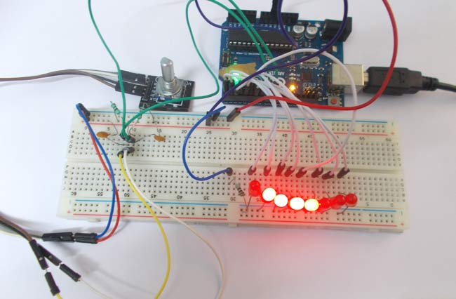
In this project we have interfaced a ROTARY ENCODER with ARDUINO Uno and developed a LED chaser circuit which is controlled by the rotary encoder. 
ROTARY ENCODER is used to know the position of movement and angular movement of a motor or axis. It’s a three terminal device usually, with power and ground pins there are total 5 terminals.

Check out the demonstration video on youtube:  

For the complete project with circuit diagram and code, visit: Arduino LED Chaser Project

Saturday, 12 September 2015

Simple Audio Amplifier Circuit using IC LM386

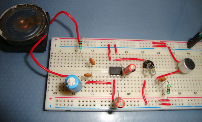
Simple Mic audio amplifier can amplify sound that is given from Microphone. This circuit can be used as “Small mic and loudspeaker system” for a small space like a room. This circuit can also be used in many applications like portable music players, intercoms, radio amplifiers, TV sound systems, Ultrasonic drivers etc. It can also be used as sound sensor for microcontrollers. It is inexpensive, low power operated and only need few components to work. This circuit is based on LM386 IC to amplify sound.

Here is the demonstration video:

Find here the circuit diagram and explanation of this simple LM386 audio amplifier circuit

For more electronic circuits, visit Circuit Digest

Saturday, 5 September 2015

Easy Electronic Circuits and Projects

Laser Based Security Alarm Circuit

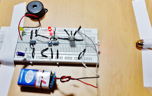
In this laser security alarm circuit , [Saddam] has used LM358 Dual Comparator IC for comparing voltages coming from LDR. Comparator is configured as Non-inverting mode and one 10K potentiometer is connected at its non-inverting terminal. An LDR is used for detecting light or laser light with respect to ground through a 10K resistor. And the midpoint of LDR and resistor is directly connected to inverting terminal of comparator.  A red LED is connected at output pin of comparator for indicating intruder detection. A mono-stable multi-vibrator is also used for activating buzzer and LED for a time period

Day and Night Indicator

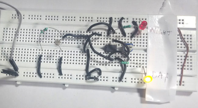
In this day and night indicator project, [Saddam] has made a circuit which will indicate if there is a dark or light in the surroundings. Some applications of this circuit, are street light controlling, home/office light controlling, day and night indicators, etc. Check out the complete post on above link.


Dancing LED Circuit

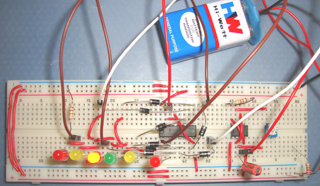
This Dancing LED circuit is used for decorative purpose and looks very good when these LEDs glow in sequential manner. We can create many kind of Dancing LEDs patterns for decoration. In this particular circuit, we have created a pattern in which 6 LEDs are illuminating in forward and reverse order. To create this circuit we have mainly used 555 timer IC and 4017 IC.

LED Chaser Circuit

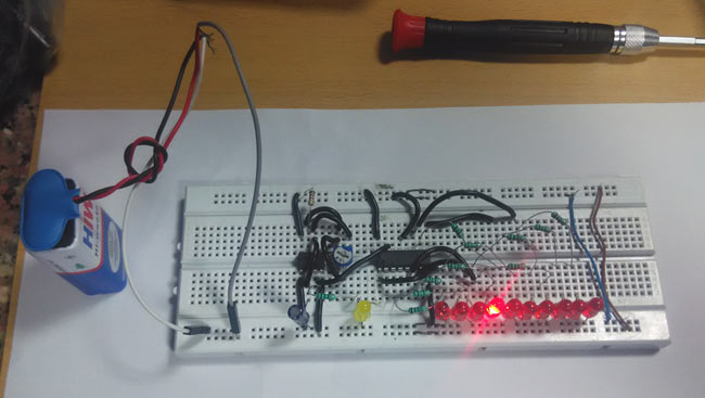
You may have seen different kinds of decoration lighting patterns. In this LED chaser circuit, [Saddam] have created an interesting LED blinking pattern by using a 555 timer IC and Decade Counter IC CD 4017.

Remote Controlled Light Switch

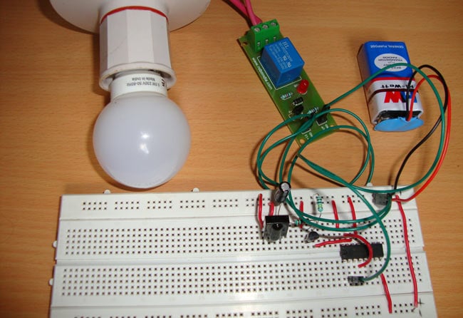
In this remote controlled switch circuit, [Jayant] have used a TV remote to ON/OFF the AC light by pressing any button of remote, and using the TSOP1738 at receiver end. Receiver circuit is connected to AC appliance via Relay, so that we can control the light remotely. We have used IC 4017 to convert it into a push ON, push OFF switch.


Sunday, 30 August 2015

Demonstration of Logic Gates

NOT Gate
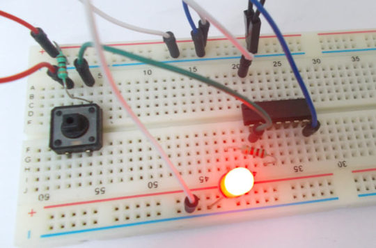
NOT gates are simply inverters. They simply invert the input logic for the output. Here we are going to use 74LS04 IC for demonstration. This IC has 6 NOT gates in it. These SIX gate are connected internally.
Here is the breadboard image of a NOT gate circuit.

You can find the explanation of this circuit: NOT Gate Circuit

NAND Gate
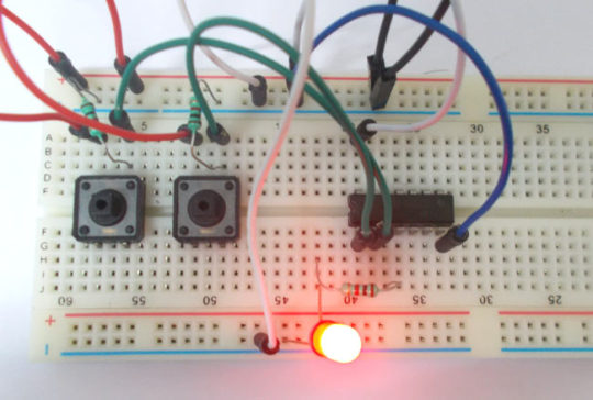
This gate is mainly used in applications where there is a need for mathematical calculations. So calculators, computers and many digital applications use this gate. 

Here you can find the circuit diagram and detailed explanation of this Circuit: NAND Gate

XOR Gate
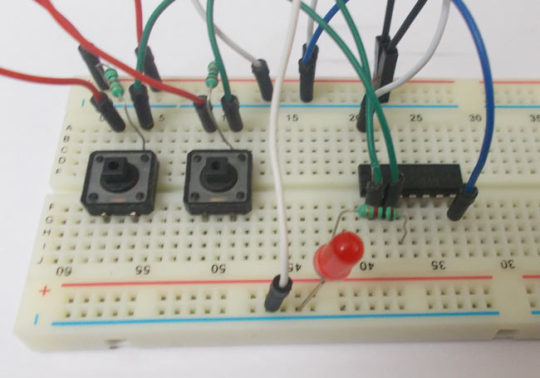
This gate is mainly used in applications where there is a need for mathematical calculations. So in calculators, computers and many digital applications use this gate.
Here we are going to use 74LS86 IC for demonstration, this chip has 4 EX-OR gates in it.


Wednesday, 26 August 2015

Reverse Car Parking Aid - Circuit Diagram

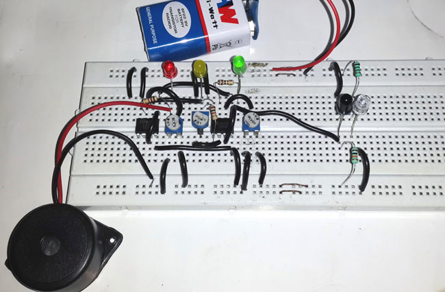
This reverse car parking assistant can protect your car from any damage while reverse parking. Though modern cars incorporate various reverse car parking sensors and cameras, this hobby circuit could be interesting and handy for many of us. It indicates the distance of car from any object and raise an alarm when it reaches close to the wall or the object and needs to be stopped. .

Here are the quick easy steps and a detailed explanation to understand the concepts and working of this circuit.