Showing posts with label RFID Technology. Show all posts

Wednesday, 11 March 2026

Arduino Automatic Toll Gate System Project with RFID Payment and Servo Control

Automatic Toll Gate System Project using Arduino

Toll collection is a common process on highways where vehicles stop to pay a fee before continuing their journey. Traditional toll booths often require manual payment, which can lead to traffic delays and long queues. Automation helps solve this problem by making the process faster and more efficient.

In this project, we build an Automatic Toll Gate System using Arduino that detects vehicles, reads RFID cards, verifies payment, and opens the gate automatically. This project is a great introduction to real-world automation using sensors, RFID technology, and microcontrollers.

It is especially suitable for students, beginners, and Arduino enthusiasts who want to understand how simple electronics can automate everyday systems.

What is an Automatic Toll Gate System?

Circuit Diagram Automatic Toll Gate System using Arduino

An automatic toll gate system allows vehicles to pass through a toll booth without manual payment handling. Instead of cash transactions, the system uses RFID cards that store user information and balance.

When a vehicle approaches the toll gate, an IR sensor detects its presence. The driver then places an RFID card near the reader. The system scans the card and checks if it is valid and has enough balance to pay the toll.

If the card is valid and the balance is sufficient, the toll amount is deducted automatically. The gate then opens using a servo motor, allowing the vehicle to pass. After the vehicle crosses the gate, another sensor detects its exit and the gate closes again.

This process makes toll collection quick, automatic, and contactless.

Components Required

Components Automated Toll Gate RFID

The project uses simple and easily available components, including:

  • Arduino Uno
  • RFID RC522 Reader Module
  • RFID Cards or Tags
  • Two IR Sensor Modules
  • SG90 Servo Motor
  • Red LED and Green LED
  • Breadboard and Jumper Wires
  • 5V Power Supply or USB Power

The Arduino acts as the central controller, while the RFID module verifies the card. IR sensors detect vehicles, and the servo motor controls the gate.

Working of the Automatic Toll Gate System

Block Diagram

The system works in a sequence of simple steps.

First, the toll gate remains closed while the system waits for a vehicle to arrive. When a vehicle approaches, the entry IR sensor detects it and signals the Arduino to begin the authentication process.

Next, the driver scans the RFID card. The RFID reader reads the card’s unique ID and sends it to the Arduino. The program compares this ID with stored card IDs and checks the available balance.

If the card is valid and has enough balance, the toll amount is deducted. The green LED turns on, and the servo motor rotates to open the gate.

The vehicle then passes through the gate. When the vehicle crosses the exit IR sensor, the Arduino receives a signal indicating that the vehicle has left the toll area. The servo motor then moves back to close the gate, and the system resets for the next vehicle.

If the card is invalid or the balance is insufficient, the red LED lights up and the gate remains closed.

Arduino Code Overview

The Arduino code controls the entire toll system. It starts by including libraries required for SPI communication, RFID reading, and servo motor control.

In the setup section, the Arduino initializes all connected hardware components, including the RFID reader, sensors, LEDs, and the servo motor.

The loop function continuously checks whether a vehicle is detected by the entry IR sensor. When a vehicle is detected, the system waits for an RFID card scan.

If the scanned card matches a stored card and has sufficient balance, the Arduino opens the gate. Otherwise, access is denied.

Real-World Applications

Although this is a learning project, the concept is widely used in real life. Automatic toll collection systems are used on highways to reduce congestion and speed up vehicle movement.

Similar RFID-based systems are also used in parking lots, office buildings, gated communities, and industrial facilities to control vehicle access.

Conclusion

The Automatic Toll Gate System using Arduino is a simple and practical project that demonstrates how automation works in real-world applications.

By combining RFID technology, sensors, and motor control, the system can detect vehicles, verify payments, and operate a toll gate automatically. This project helps beginners learn important concepts such as Arduino programming, sensor integration, and RFID communication.

With further improvements like IoT connectivity or LCD displays, this project can easily be expanded into a more advanced smart toll management system.

https://circuitdigest.com 

Robotics Projects |Arduino Projects | Raspberry Pi Projects|

Wednesday, 2 July 2025

RFID-Based Attendance System with Arduino


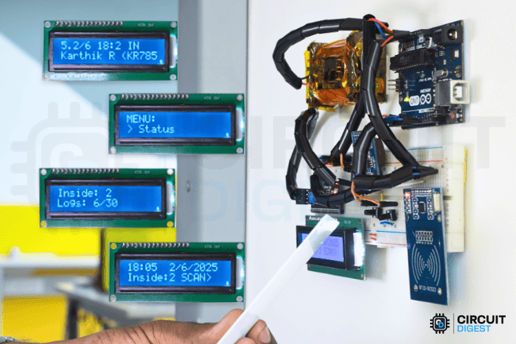
Keeping track of attendance should not feel like a daily hassle. Whether you are running a classroom, managing a small office, or organizing a community event, a simple, low-cost solution can go a long way. This RFID based attendance system using Arduino reads RFID cards to automatically log check-ins and check-outs, shows updates on an LCD, and stores attendance logs with real-time stamps using an RTC module. It's completely offline and stores data locally, so no need for an internet connection. The total cost is just around $30.

Why Choose Arduino for DIY RFID Attendance Tracker?

Arduino gives you full control over the system’s features without depending on expensive or limited commercial options. The MFRC522 RFID reader is accurate, and combining it with real-time clock and EEPROM modules means your data is both timestamped and safely stored, even during a power cut. Plus, once built, this setup is fully reusable and expandable for future upgrades like IoT integration or door control.

Key Features of RFID based attendance system

  • Automated RFID card scanning for both entry and exit
  • Real-time timestamp logging using DS1307 RTC
  • Local data storage with EEPROM, survives reboots
  • LCD display for live updates
  • Menu navigation via push buttons or serial monitor
  • Customizable card programming with personal data

Overview-Image-of-RFID-Based-Attendance-System-Using-Arduino

Components You’ll Need

  • Arduino Uno
  • MFRC522 RFID Reader
  • DS1307 RTC Module (with built-in AT24C32 EEPROM)
  • 16x2 I2C LCD Display
  • Push Buttons (x2)
  • RFID Cards/Tags
  • Breadboard, jumper wires, and 5V–12V power supply

RFID-Attendance-System-Using-Arduino
Real-World Applications

  • Classrooms – Track student attendance and prevent proxy entries
  • Offices – Log employee in/out times without manual input
  • Gyms & Clubs – Track member usage, ensure hygiene with contactless logging
  • Workshops – Monitor visitor entry or workshop sessions
  • Healthcare & Industry – Touchless logging for safety zones or shift tracking
This RFID based attendance system using Arduino is a great DIY project for anyone looking to solve a real problem while learning valuable electronics and programming skills. It’s affordable, fully offline, and scalable. Once set up, it can handle real-time check-ins, and you will know exactly how every part works.

Wednesday, 5 March 2025

How to Build an RFID Door Lock System Using Arduino


Learn how to build an  RFID-based door lock system using an Arduino Uno, an RFID module, and a servo motor. The system scans an RFID card, checks its ID, and unlocks the door if it’s authorized. This setup is useful for home security, office access control, and smart automation projects.

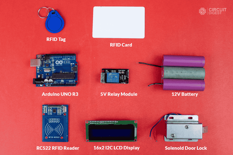
Components Required

  • Arduino Uno (or compatible board)
  • RC522 RFID Module (to read RFID tags)
  • RFID Cards & Key Fobs (for authentication)
  • Servo Motor (to control the lock)
  • Buzzer & LED Indicators (for access feedback)
  • Jumper Wires & Breadboard (for connections)


Components Required to make RFID Door Lock System Using Arduino
Components Required to make RFID Door Lock System Using Arduino

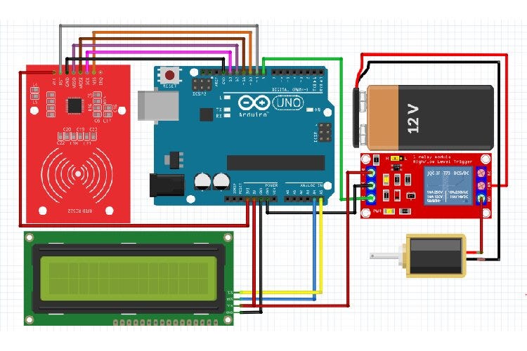
RFID Door Lock System using Arduino Circuit Diagram


Circuit Diagram RFID Door Lock System using Arduino
Circuit Diagram RFID Door Lock System using Arduino

The RFID door lock system works by scanning an RFID card or key fob using the RC522 RFID module. When a card is scanned, the Arduino reads its unique ID and checks if it matches a pre-stored authorized ID. If the card is recognized, the servo motor unlocks the door, allowing access. If the card is not authorized, the system triggers a buzzer and an LED indicator to signal access denial. After a short delay, the lock resets and waits for the next scan, ensuring continuous operation.

Arduino Code to Read RFID Card UID

To find your authorized RFID card UID, compile and upload the code to your Arduino. No hardware modifications are needed.

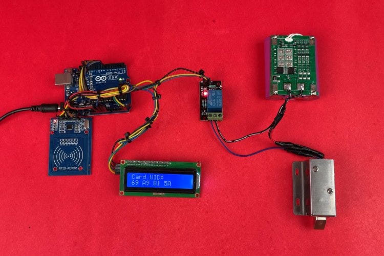
Complete Hardware Setup of RFID Door Lock System using Arduino
Complete Hardware Setup of RFID Door Lock System using Arduino

Code for RFID Door Lock System using Arduino

This Arduino-based RFID door lock system reads an RFID card’s UID, checks it against a predefined UID, and unlocks the door for 10 seconds using a relay and solenoid lock while displaying the status on an LCD.

Step-by-Step Guide

Step 1: Setting Up the Hardware

Start by assembling the required components. Connect the RC522 RFID module to the Arduino Uno using SPI communication. Attach the relay module and solenoid lock for door control, and connect the LCD display to show access status. Ensure the power supply is stable for reliable operation.

Step 2: Uploading the UID Retrieval Code

To get the unique ID (UID) of your RFID card, compile and upload the UID retrieval code to the Arduino. This step doesn’t require any hardware modifications. Once uploaded, open the Serial Monitor in the Arduino IDE to view the scanned UID.

Step 3: Storing the Authorized UID

After retrieving the UID, update the main code by replacing the default UID with your card’s UID. This ensures that only the authorized card can unlock the door. Save and re-upload the modified code to the Arduino.

Step 4: Implementing the Door Lock System

The main program continuously scans for RFID cards. When a card is detected, the Arduino checks if its UID matches the stored UID. If authorized, the relay activates the solenoid lock, unlocking the door for 10 seconds. Meanwhile, the LCD display updates the door status.

Step 5: Testing and Final Adjustments

Test the system by scanning different RFID cards. If unauthorized, the lock remains closed, and the system displays an access denied message. Adjust the servo angles, delay timings, or security features as needed for better performance.


Final Testing of our RFID Door Lock System
Working Demo video : 

Enhancements & Customization

  • Store multiple RFID card IDs for multi-user access.
  • Add an OLED display to show authentication messages.
  • Integrate Wi-Fi or Bluetooth for remote access control.
  • Connect to a database for logging entry records.

This RFID-based door lock system offers a simple yet effective way to manage access control. It can be expanded with additional features to enhance security and functionality. 


Learn more about this tutorial  How to make an RFID Door Lock System using Arduino?

Get the more projects with full code and schematics on our https://circuitdigest.com 

Robotics Projects |Arduino Projects | Raspberry Pi Projects|


Thursday, 22 February 2024

Popular Raspberry Pi Projects | Full Tutorial with Code and Circuit Diagram

Raspberry Pi – a small, but mighty computer that fits in the palm of your hand, complete with the ability to connect to a monitor, keyboard, and mouse. It's affordable and super easy to use, even if you're not a tech whiz. Whether you're a kid or an adult, Raspberry Pi is designed for everyone to have fun while learning about computers and technology. It's capable of doing all sorts of cool things, like teaching you how to code, helping you build your own games, creating smart home gadgets, and even making your own robots. The possibilities are endless.

The main objective of this article is to showcase the practical applications of Raspberry Pi and provide detailed tutorials through informative articles. Let’s get going…


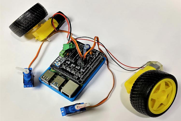
DIY Raspberry Pi Motor Driver HAT


A Raspberry Pi HAT is an add-on board for Raspberry Pi with the same dimensions as Pi. There are many Raspberry Pi HATs available in the market. In this tutorial, we are going to build a Raspberry Pi Motor Driver HAT to drive DC and Stepper motors. This HAT features an L293D motor driver IC, a 16x2 LCD Display Module, four push-buttons, and additional pins for a SIM800 Module with a 3.3V regulator, making it perfect for robotics projects and so on…


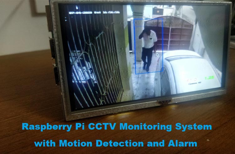
Raspberry Pi CCTV Monitoring


If you do not have a CCTV installed, you can still build a Raspberry Pi Surveillance system by connecting USB cameras directly to your Pi. Create a versatile motion detection system for CCTV surveillance using OpenCV and Raspberry Pi. Additionally, include an alarm feature – a buzzer – to alert the user with a beep upon detecting activity. Know more about the Setting up of Raspberry Pi and OpenCV for monitoring.


Push-Up Counter using Raspberry Pi 


Be ready to track your progress seamlessly. Simply follow our step-by-step tutorial to set up the system, and start counting your push-ups with a Raspberry Pi 4 and Pi camera module, along with OpenCV and MediaPipe installed…. Using Raspberry Pi and MediaPipe Pose estimation package, you can accurately count push-ups in real-time, making your workouts more efficient.


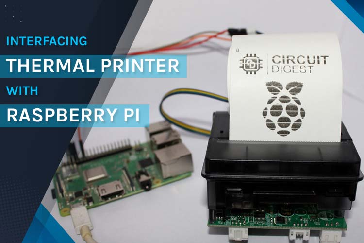
Thermal Printer with Raspberry Pi


Learn how to interface a Thermal Printer with Raspberry Pi using hardware serial communication, to print a test receipt that contains various elements like a Logo, a QR Code, or barcode along with various other text and graphical characters. This project offers a practical and versatile solution for printing receipts, tickets, and more. Check out the full tutorial for step-by-step instructions… and start printing with Raspberry Pi 


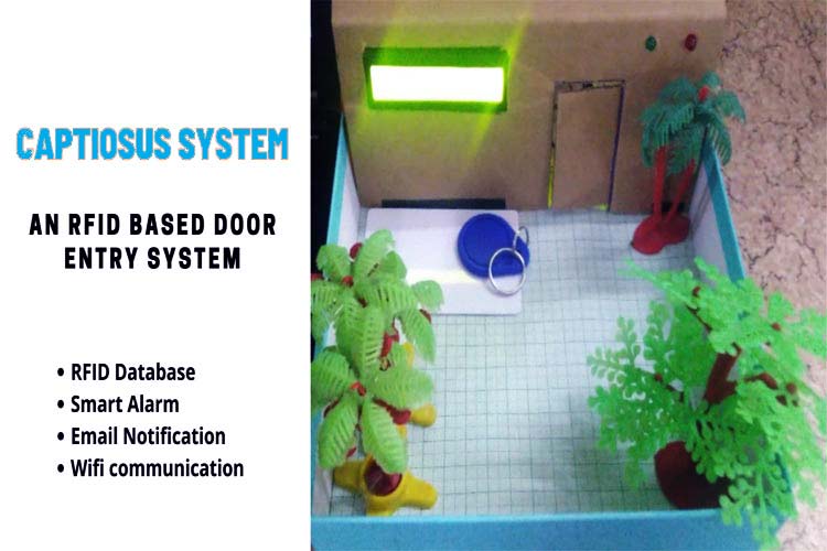
Door Lock System using Raspberry Pi


The Captiosus System: an RFID-based door lock and entry system designed to offer enhanced security and convenience for homes and other premises. This system utilizes RFID tags as keys, allowing for controlled access through an RFID scanner. Additionally, it features an alarm system to deter unauthorized entry attempts.

Complete Tutorial- https://circuitdigest.com/microcontroller-projects/rfid-based-door-lock-system


 Raspberry Pi based Autonomous UV Robot


The autonomous UV robot project offers a cost-effective solution for disinfection needs, featuring a range of components like Raspberry Pi, Arduino UNO, and UV lights. It utilizes state-of-the-art SLAM technology for safe navigation, ensuring workers are not exposed to harmful UV light. With built-in sensors and wireless connectivity, the robot provides real-time status updates via a mobile app.


Complete Tutorial- Autonomous UV Robot with SLAM


Raspberry Pi Internet Radio and Streaming Station


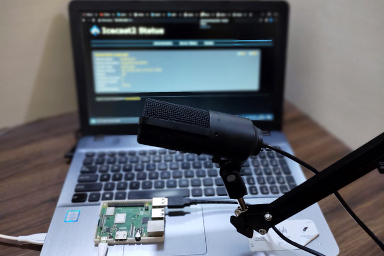
Setting up a Raspberry Pi streaming station, You'll need a Raspberry Pi, a USB microphone, and an Internet connection. After updating your Pi, you'll install and configure DarkIce and Icecast, then test the setup via web browser access.

This tutorial demonstrates setting up a Raspberry Pi streaming station using DarkIce and Icecast. 


We hope you found this tutorial helpful and enjoyable. If you have any questions or comments, please leave them in the comment section below. Additionally, you can visit our website for technical assistance and to explore our latest project.