Showing posts with label electronic circuits. Show all posts

Tuesday, 24 March 2026

Simple Optocoupler Tester Circuit for Quick and Reliable Testing

Optocouplers are small but critical components used in many electronic circuits for isolation and signal transfer. The tricky part? When they fail, they usually don’t show any visible signs. Everything looks fine on the outside, but internally, either the LED or the phototransistor might stop working.

That’s where a simple optocoupler tester circuit becomes extremely useful. Instead of guessing or relying only on a multimeter, this small tester gives you clear results in seconds.

What This Tester Does

This optocoupler tester is designed to quickly check whether an optocoupler is working properly or not. It verifies two key things:

  • Whether the internal LED (input side) is functioning
  • Whether the output side responds to the light

The circuit is simple, battery-powered, and doesn’t require any measuring tools. It’s perfect for lab use, repair work, or even checking salvaged components.

How the Circuit Works


The working principle is based on optical isolation.

When you press the push button:

  • Current flows through the internal LED of the optocoupler
  • A red LED glows, indicating the input side is active
  • The emitted light triggers the output transistor
  • A green LED turns ON if the output side is working

So, in just one press, you get a complete functional check.

The results are easy to understand:

  • Both LEDs ON → Optocoupler is good
  • Only red LED ON → Output side is faulty
  • No LEDs ON → Input LED or connection issue
  • Green LED only → Possible wiring error or short

This makes troubleshooting fast and beginner-friendly.

Components Used

The best part of this project is how simple it is.

You only need:

  • Optocoupler (for testing)
  • Red LED (input indication)
  • Green LED (output indication)
  • Push button
  • 3.7V Li-ion battery
  • Two 470Ω resistors
  • IC sockets (4-pin & 6-pin)
  • Dot board

Using IC bases is a smart choice here. It lets you test multiple optocouplers without soldering or risking heat damage.

Why Not Just Use a Multimeter?

You can test an optocoupler using a multimeter, but it has limitations.

A multimeter:

  • Can check only the input LED properly
  • Cannot fully verify the output response
  • Requires manual probing and interpretation

This tester, on the other hand:

  • Checks both input and output together
  • Gives instant visual results
  • Takes less than 2 seconds per test

So for regular use, a dedicated tester is much more practical.

Where This Is Useful

This simple circuit is surprisingly helpful in many situations:

  • Electronics labs
  • Repair and maintenance work
  • Testing bulk components
  • Educational projects
  • Verifying reused or salvaged parts

It saves time and prevents faulty components from being used in circuits.

This Optocoupler Tester Circuit is a perfect example of a small project that solves a real problem. It’s simple, low-cost, and extremely practical.

Instead of spending time guessing or troubleshooting blindly, you get a clear pass/fail result instantly. And once you build it, you’ll find yourself using it again and again.

If you’re working with optocouplers regularly, this is definitely a must-have tool on your workbench.

https://circuitdigest.com 

Robotics Projects |Arduino Projects | Raspberry Pi Projects|

Saturday, 31 May 2025

Understanding Flip-Flops in Digital Electronics

Flip Flop in Digital Electronics

Flip-flops are basic building blocks in digital electronics that work as simple 1-bit memory devices. In electronics Flip-Flop is "A bistable device with synchronous inputs that changes state only at specified transitions of a clock signal" (IEEE Standard 91/1984)". Unlike regular logic gates that respond instantly to inputs, flip-flops can store a value, either 0 or 1, and keep it until something changes it, usually through an input signal and a clock pulse. 

Because of this ability to hold information, they’re used in many sequential circuits like counters, registers, and parts of memory in microprocessors. The following tutorial will give you a complete understanding of Flip-Flops in Digital Electronics.

Difference Between Latch and Flip-Flop

A latch is level-triggered, meaning its output changes as long as the input is active. A flip-flop is edge-triggered, updating its output only on a specific clock edge (rising or falling).

Transistors → Logic Gates → Latches → Flip-Flops

Types of Flip Flops in Digital Electronics

  • SR Flip-Flop: This is the simplest type of flip-flop that uses Set (S) and Reset (R) inputs to store a bit. It’s great for basic memory storage, but it gets a bit tricky when both inputs are active at the same time.

SR flip-flop diagram


  • D Flip-Flop: Captures the value present at its D input when a clock pulse occurs, and this value is maintained as the output until the next clock pulse. This characteristic makes the D flip-flop a fundamental building block in registers, shift registers, and various other memory devices. 

d flip-flop circuit diagram


  • JK Flip-Flop: Think of it as an improved version of the SR flip-flop that avoids the “invalid” state issue. It can toggle, set, or reset based on its J and K inputs and is very versatile in counters.

jk flip-flop circuit diagram


  • T Flip-Flop: Toggles the output on each clock cycle when T is high. It is particularly useful in applications like counters and control circuits.

t flip flop circuit diagram

Applications of Flip-Flops

  • Registers
  • Counters
  • Finite State Machines (FSMs)
  • Pipeline stages

Understanding flip-flops is crucial for anyone interested in digital electronics, as they form the basis for more complex sequential circuits and systems.

For a more detailed explanation and practical demonstrations, refer to the full article on Circuit Digest.: Flip-Flop in Digital Electronics: Types, Truth Table, Logic Circuit and Practical Demonstration


Monday, 31 July 2017

3 Basic Electronics Circuits to Learn Electronics

Here are 3 simple electronic circuits by using basic electronic components.

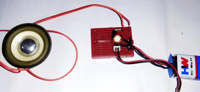
1. Simple Preamp Circuit


"Sometimes we use a Preamp Circuit in circuits for pre-amplification of weak signal when the audio source sound level is too low. Pre-amlification of low level signals is necessary before feeding them into a power source, for clear and noiseless sound." So here we will build this Simple Preamplifier Circuit using NPN transistor BC547.

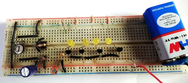
2. Bike Turning Signal


This fancy Car/Bike Turning Indicator Circuit uses a 555 Timer IC along with four yellow color LEDs glowing one by one in a particular pattern and we can control the speed or frequency of this LED indicator by simply turning a Potentiometer. This works in the similar pattern in which bike or car's turning signal works. Here you can find all the required details to build this circuit.

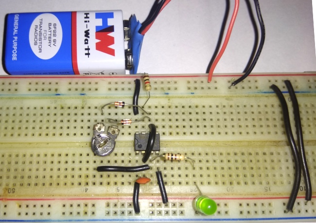
3. PWM Generator Circuit


PWM is very important concept in electronics engineering. To understand this concept and make a simple circuit with this, we used a 555 timer IC along with a potentiometer, a capacitor and few registers which generates PWM signal. You can learn about PWM concept with building this basic circuit.