Showing posts with label PWM. Show all posts

Wednesday, 14 February 2024

Manual Techniques for Controlling Multiple Servos


The PCA9685 16-channel 12-bit PWM/Servo Driver module provides precise control over multiple PWM outputs, making it ideal for applications requiring accurate control over servos, LEDs, and various devices. This project aims to explore its functionalities, particularly focusing on how to control servo motors, to offer users a comprehensive understanding of its capabilities.

Required Components:

  • Arduino Uno R3
  • 8 * SG90 Servo Motors
  • PCA9685 16-Channel Module
  • External 5v Adapter
  • Jumper Wires

Interfacing Servo with Arduino:

Servo motors utilize PWM signals for precise control over their rotation angle. They typically feature three wires: VCC for power, GND for ground, and PWM for control signals. Connecting a servo to an Arduino involves supplying power and linking the PWM wire to a digital PWM pin. The Servo.h library enables servo control by uploading the Sweep Sketch to the Arduino IDE.

Arduino's limited number of PWM output pins poses challenges for scenarios requiring control over multiple servos. Complex techniques like multiplexing or software PWM may not offer accurate servo control. The PCA9685 module effectively addresses this limitation.

The PCA9685 module simplifies servo control by providing 16 free-running PWM outputs using only two pins, operated through I2C communication. It supports a wide range of applications, including robotics, automation, and lighting control. The module's features, such as a built-in clock and compatibility with 3.3V microcontrollers, enhance its versatility.

Programming the PCA9685 with Arduino:

Utilizing the Adafruit_PWMServoDriver library facilitates easy control of the PCA9685 module. By initializing the module and setting the PWM frequency, servo control becomes straightforward. The setPWM() function allows for precise control over servo angles, enabling smooth and synchronized motion. Prior to powering the setup, thorough checking of connections is crucial. Eight servos are connected to channels 0 to 7 of the PCA9685 module, powered by an external adapter for sufficient power. Monitoring angle and pulse data through the serial display provides insights into servo motion.

In summary, the PCA9685 16-Channel Servo Driver module offers a practical solution for precise control over multiple PWM outputs, particularly suited for applications involving servo motor control. Throughout this project, we've explored its functionalities, including interfacing methods and programming with Arduino. 


Monday, 31 July 2017

3 Basic Electronics Circuits to Learn Electronics

Here are 3 simple electronic circuits by using basic electronic components.

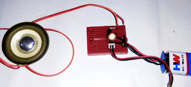
1. Simple Preamp Circuit


"Sometimes we use a Preamp Circuit in circuits for pre-amplification of weak signal when the audio source sound level is too low. Pre-amlification of low level signals is necessary before feeding them into a power source, for clear and noiseless sound." So here we will build this Simple Preamplifier Circuit using NPN transistor BC547.

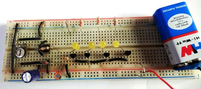
2. Bike Turning Signal


This fancy Car/Bike Turning Indicator Circuit uses a 555 Timer IC along with four yellow color LEDs glowing one by one in a particular pattern and we can control the speed or frequency of this LED indicator by simply turning a Potentiometer. This works in the similar pattern in which bike or car's turning signal works. Here you can find all the required details to build this circuit.

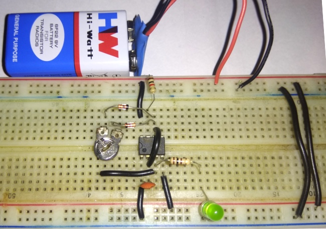
3. PWM Generator Circuit


PWM is very important concept in electronics engineering. To understand this concept and make a simple circuit with this, we used a 555 timer IC along with a potentiometer, a capacitor and few registers which generates PWM signal. You can learn about PWM concept with building this basic circuit.

Friday, 22 April 2016

Getting Started with Arduino Due - Connecting LED's and PWM Tutorial

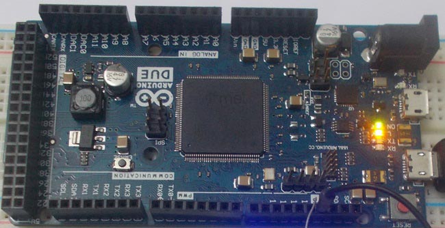
Let's first have a basic introduction of Arduino Due Board. It is an ARM controller based board designed for electronic Engineers and Hobbyists. ARM architecture is very influential in modern electronics. We are using the ARM architecture based controllers everywhere. For example we are using ARM controllers in our mobiles, iPods and computers etc. If someone wants to design industrial systems, it must be on ARM controllers. ARM controllers are very important because of the frequency of their operation and data bus size.
Here is a simple tutorial to blink an LED for every 1000ms.We will connect an LED at PIN13 through a 220Ω current limiting resistor.

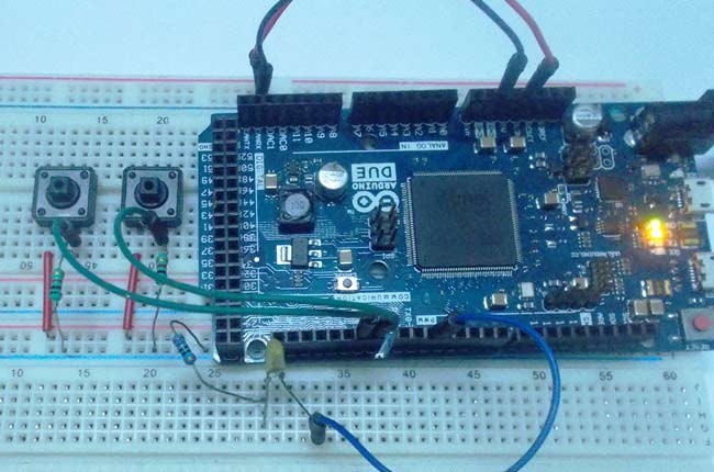
Now lets check this experiment to understand the PWM (Pulse Width Modulation) concept in Arduino Due board.

The circuit is connected on breadboard as per the connections shown in above image. However one must pay attention during connecting the LED terminals. Although the buttons can show bouncing effect but in this case it does not cause considerable errors, so we need not worry this time.

Check here the complete tutorial: PWM with Arduino Due