Showing posts with label PCB. Show all posts

Thursday, 15 May 2025

ESP32 DIY Desktop Weather Station

DIY Desktop Weather Station
Want to keep an eye on the weather without constantly checking your phone? 
This DIY Desktop Weather Station has you covered! It features an ESP32-S3 board that connects to Wi-Fi and fetches real-time weather updates, like temperature, humidity, and current conditions, directly from the OpenWeatherMap API. For indoor readings, it includes a built-in HPP845E031R4 sensor that monitors your room's temperature and humidity. Its E-Ink display consumes very little power and can operate for days on a single charge. After each weather update, it automatically enters sleep mode to conserve even more energy.

Components Required

  • ESP32-S3-WROOM-1-N16R8
  • 4.2" EPD (E-Ink) Display
  • HPP845E031R4 Temperature & Humidity Sensor
  • ADP124ACPZ 3.3V LDO Regulator
  • MAX1898 Battery Charger IC

Desktop Weather Station Schematic Diagram

The weather station uses a custom-designed multi-color PCB that keeps the build neat, compact, and professional-looking. The PCB was designed using KiCad, and its dimensions are approximately 105mm × 90mm, making it perfect for desktop use. The design not only simplifies assembly but also adds a polished finish to the final product.
Desktop Weather Station Schematic Diagram

Assembling the Desktop Weather Station

Once the components are soldered and the board is assembled, simply power up the device and place it on your desk. The ESP32-S3 will handle all the background tasks, connecting to Wi-Fi, retrieving weather data, displaying it clearly on the E-Ink screen, and then entering sleep mode to save power.

Assembling the Desktop Weather Station PCB

It’s a compact, energy-efficient, and functional weather station that updates you with real-time information both indoors and outdoors. Whether you're building it for fun, education, or smart home integration, it’s a rewarding and practical DIY project.

The ESP32-S3-based Desktop Weather Station is a sleek and low-power solution for real-time weather updates. It combines wireless connectivity, local sensing, and an E-Ink display for a complete smart desktop gadget. With its clean PCB design and minimal component list, it’s perfect for electronics enthusiasts and makers. Whether for personal use or a tech-savvy gift, this project is both useful and fun to build.

For full assembly details and code:  How to Build a Desktop Weather Station Using ESP32 and E-ink Display


Tuesday, 27 July 2021

DIY Portable Ultrasonic Digital Ruler using ATtiny85 Microcontroller


Distance measurement of an object in the path of the person, equipment, or a vehicle or moving object is used in a large number of applications such as robotic movement control, vehicle control, blind man’s walking stick, medical equipment, etc. There are many methods available for distance measurement but measurement using Ultrasonic sensor is one of the cheapest among other options. In this project, we are going to use HC-SR04 Ultrasonic Sensor with ATtiny85 microcontroller IC and OLED display module to build a digital ultrasonic ruler.


For the circuit diagram, code and gerber files, please visit the project page: DIY Digital Ruler


For more electronics project, visit: projects page


Monday, 24 May 2021

DIY Raspberry Pi UPS HAT – An Uninterrupted Power Supply to Keep your Pi Safe during Power Failure


Raspberry Pi is a small or mini-computer that can be used in different types of small to large embedded, IoT, Industrial IoT applications. As this is a computer that could run different operating systems, a shutdown of this minicomputer is an important thing to ensure that everything is saved, the operating system properly ended all required tasks, and it is safe to turn the device off. Uncertain failure of power could damage the Pi as well as the operating system could also break down. Previously we have built many Raspberry Pi Projects and most of them needed to work 24x7 so, this project can act like a Raspberry pi UPS hat and can be used to keep our raspberry pi on during power failure.

View the full project tutorial:

DIY Raspberry Pi UPS

Thursday, 5 November 2020

How to Build a Compact and Low Power Solid-State Relay to Control AC Home Appliances using ESP8266

The best alternative for an electromechanical relay is a solid-state relay. A solid-state relay is a type of semiconductor-based relay that can be used as a substitute for an electromechanical relay to control electrical loads.


In this project, we will make a Solid-State Relay using a single component and we will control an AC load in 230VAC operation. The specification used here is limited, we have chosen 2A of Load to be operated using this Solid-State-Relay. The aim is to build a compact PCB for a solid state relay that could be directly interfaced and controlled with the 3.3V GPIO pins of Nodemcu or ESP8266. To accomplish that we have fabricated our PCB boards from PCBWay and we will assemble and test the same in this project.
View the full project tutorial

Watch the video below:

Thursday, 4 June 2020

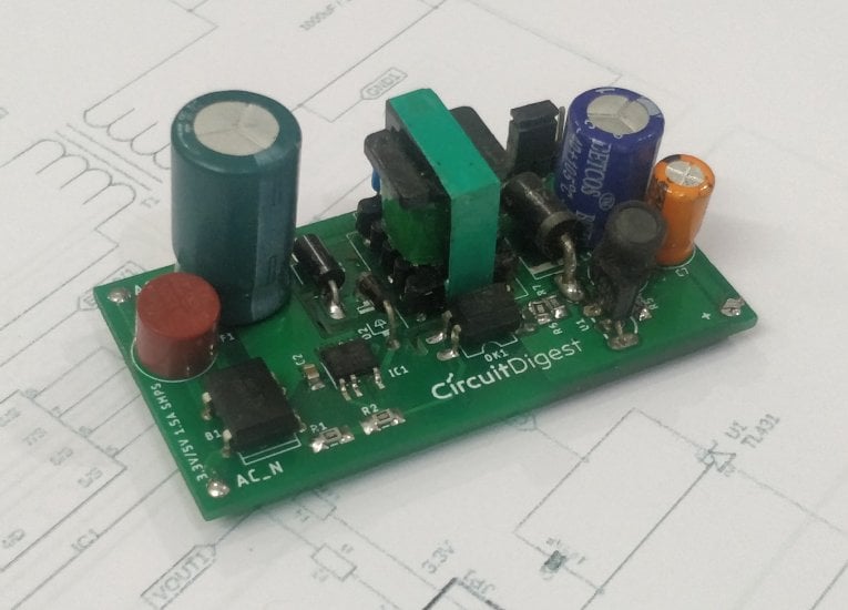
Design your own Compact 5V/3.3V SMPS Circuit for Embedded and IoT Projects


Here we will build a SMPS that can be used for general purposes and has a simple module shape to be used in space-related situations. Nowadays, the Internet of Things uses various wifi-based processors like NodeMCU, ESP32, and ESP12E, etc. which operate on 5V or 3.3V. These modules are highly compact and hence to power these boards, it makes sense to use smaller SMPS circuits that can go on the same board, instead of using a separate SMPS circuit. Hence in this article, we will learn how to build a SMPS circuit that can either output 5V or 3.3V (hardware configurable using jumper), the circuit design and PCB layout is also provided, so you can simply port this into your existing design. Here our PCB boards are manufactured by PCBGoGo, a china based low cost high quality PCB prototype and PCB assembly service company.

Tuesday, 5 March 2019

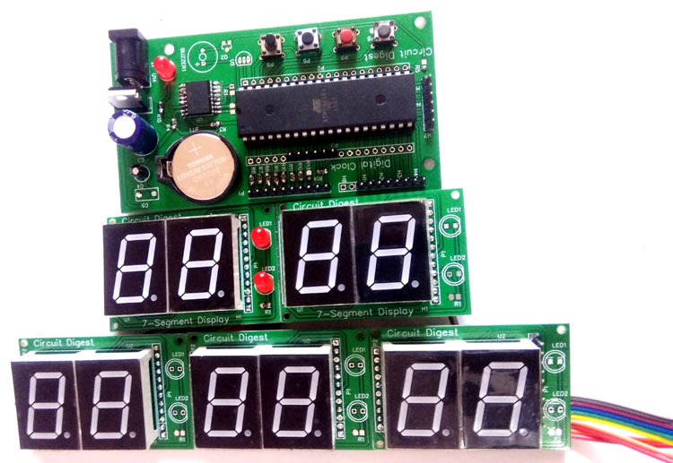
Digital Wall Clock using Atmega16 and DS3231 RTC

This is a DIY PCB project for a Digital wall clock, which is made using Atmega16 microcontroller and DS3231 RTC module.


In this Digital Clock Project, ten common anode 7-segment displays of 0.8-inch are used to display time and date. Here seven segment displays are used to show hour, minute, date, month and year. Our PCB design also has options to display seconds and temperature, which can be displayed by adding more display units.

You can watch the video below for more details of this AVR project.

Sunday, 15 January 2017

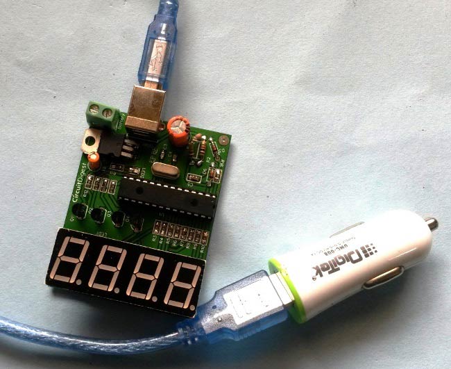
Car Battery Voltage Monitoring using PIC Microcontroller


In this project we are going to make a PIC based Car Battery Monitoring system on PCB. Here, we have designed a PCB using EASYEDA online PCB simulator and designer. This Car Battery Monitoring Circuit is used to monitor the power of Car Battery by just plugging it into the power outlet on the dashboard of a car. The PCB also has the option to use it as Voltage Measurement tool or Voltmeter without using USB car charger. We have attached a terminal block here to measure the voltage of other power sources, just by connecting two wires in it from the power source. 

Sunday, 23 October 2016

Arduino LED VU Meter on PCB

VU Meter or Volume Meter is very interesting project for music lovers. It is kind of an Equalizer, which is present in the Music systems where we can see the dancing of LEDs according to the music, if music is loud then equalizer go to its peak and more LEDs will glow, and if music is low then lesser number of LEDs shall glow. Volume Meter (VU) is an indicator or representation of the intensity of sound level over LEDs and can also serve as a volume measurement device.

DIY Arduino VU Meter

Although we can also create a simple VU meter circuit without using any microcontroller but to enhance it and work in a more beautiful way, we have designed it as an Arduino shield. Here you can find the complete DIY tutorial and a step by step guide to design the PCB layout for this VU meter.

Check it out here.


Watch the VU meter working in this video.