Showing posts with label RobotCar. Show all posts

Saturday, 18 April 2026

AI-Based Hand Gesture Control Robot Using OpenCV

Gesture control is quickly becoming a natural way to interact with machines. Instead of relying on buttons or joysticks, this project lets you control a robot using simple hand movements. By combining computer vision with wireless communication, this system creates a responsive and intuitive control experience.

This Hand Gesture Control Robot Using OpenCV project demonstrates a hand gesture control robot using OpenCV, where a laptop webcam detects hand movements and translates them into motion commands for a rover.

How the System Works

At its core, the system follows a three-stage process: gesture detection, wireless transmission, and motor execution.

A Python program running on a laptop captures live video through a webcam. Using OpenCV and MediaPipe, it detects 21 key points on the hand and determines which fingers are raised. Based on this pattern, the system identifies gestures like forward, backward, left, right, or stop.

Once a gesture is recognized, the program sends a simple command (like “F” or “L”) via serial communication to an Arduino Nano acting as a transmitter. This Arduino then forwards the command wirelessly using the nRF24L01 module.

On the robot side, another Arduino Nano receives the command and controls the motors through an L298N Motor Driver, allowing the rover to move accordingly.

Key Components

Components-Used-In-Gesture-Controlled-Robot

The setup uses easily available components, making it accessible for students and hobbyists:

  • Two Arduino Nano boards
  • Two nRF24L01 wireless modules
  • L298N motor driver
  • 4-wheel DC motor chassis
  • Laptop with webcam
  • 12V battery pack

Each component plays a specific role, from gesture processing to wireless communication and motor control.

Gesture Recognition with OpenCV

The vision system is powered by OpenCV and MediaPipe. OpenCV handles camera input and frame processing, while MediaPipe detects hand landmarks in real time.

The system identifies finger positions and converts them into commands:

  • Index finger → Forward
  • Two fingers → Backward
  • Thumb + index → Left
  • Three fingers → Right
  • Open hand or fist → Stop

This logic keeps the system simple while ensuring accurate gesture detection.

Wireless Communication

Gesture-Controlled-Robot-Transmitter

The nRF24L01 modules enable low-latency wireless communication between the controller and the robot. Commands are transmitted as single characters, keeping the data lightweight and fast.

With proper configuration, the system achieves reliable communication within a short range, making the robot feel responsive and smooth during operation.

Robot Movement and Control

On receiving a command, the rover executes it instantly. The L298N motor driver controls the direction and speed of the motors using PWM signals.

For safety and stability, the system limits motor speed to around 50%, ensuring controlled movement without overloading the hardware.

Real-World Applications

This project goes beyond just a demo and opens doors to practical applications:

  • Contactless robotic control systems
  • Assistive technology for accessibility
  • Surveillance and remote-controlled vehicles
  • Educational platforms for robotics and AI
  • Human-machine interaction research

This hand gesture control robot combines computer vision, wireless communication, and embedded systems into a single project. It offers a hands-on way to understand how modern interfaces work and how machines can respond to natural human input.

With its simple design and powerful concept, this project is a great starting point for building advanced gesture-controlled systems and exploring real-time robotics.

https://circuitdigest.com 

Robotics Projects |Arduino Projects | Raspberry Pi Projects|


Thursday, 27 February 2025

How to Build an Arduino Maze-Solving Robot – Step-by-Step Guide


Maze solving robot

Ever wondered how robots navigate complex paths without human intervention? A maze-solving robot is an autonomous bot that can find the shortest path through a maze using sensors and algorithms. In this guide, Learn how to build an Arduino-powered maze-solving robot, complete with schematics and code. 

What is a Maze-Solving Robot?

A maze-solving robot uses sensors and programming logic to detect paths, walls, and dead ends. 

Components Required

To build this project, you'll need:

  • Arduino Uno
  • IR Sensors (Line Tracking)
  • Motor Driver Module (L298N)
  • DC Motors & Wheels
  • Chassis & Battery Pack
  • Jumper Wires & Breadboard

Maze Solving Robot Circuit Diagram
Applications of Maze-Solving Robots
  • Robotics competitions
  • Automated navigation systems
  • Rescue robots in hazardous areas
  • AI pathfinding research

Wednesday, 17 April 2024

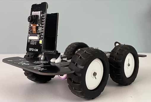
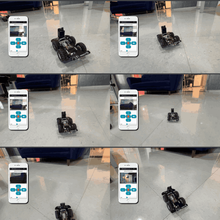
DIY WiFi-Controlled ESP32 Cam Surveillance Car: Build Your Own Remote-Control Adventure!

 This project is perfect for anyone keen on learning about ESP32-based devices and remote-controlled systems. We'll be using the ESP32 camera module to build a surveillance car that's not only energy-efficient but also budget-friendly. Let's get started!


What's the ESP32 Cam Surveillance Car All About?


The ESP32 Cam Surveillance Car project showcases the versatility of the ESP32 projects platform. It's a step-by-step guide to building a remote-controlled car and understanding its components.


Key Features and Components


ESP32 Cam Module: This is the brain of our surveillance car, providing WiFi connectivity and camera functionality.

Web Controls: Allows you to control the car remotely via a web interface—no extra hardware needed!

Affordable Design: We've designed this project with readily available components, perfect for hobbyists and learners.

Open-Source: Feel free to customize and learn from our design files and code.

Compact and Portable: Designed to be compact and easy to carry around—great for educational purposes.

Scalable and Upgradable: There's room for expansion and future enhancements.

Required Components


To build your ESP32 Cam Surveillance Car, you'll need:


ESP32 Camera Module

CH340K USB-UART controller

TP4056 Li-ion charger IC

MX1508 motor driver module

AO3401 P-MOSFET

Type C USB Connector

LiPo Battery

N20 Motors and 44mm wheels

SMD resistors, capacitors, and LEDs

Slide Switch, Connectors, Custom PCB, Mounting screws, and other tools


Circuit Design

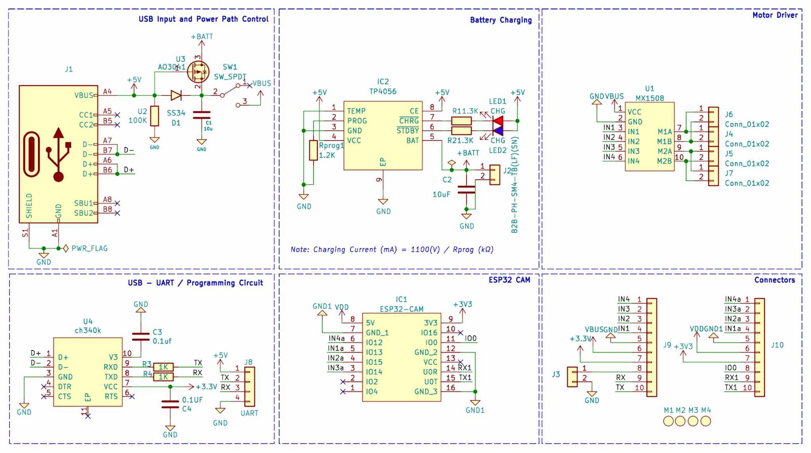
The circuit diagram is straightforward and divided into sections for USB Type C Port, Battery Charger Circuit, Programming Circuit, and Motor Driving Section.


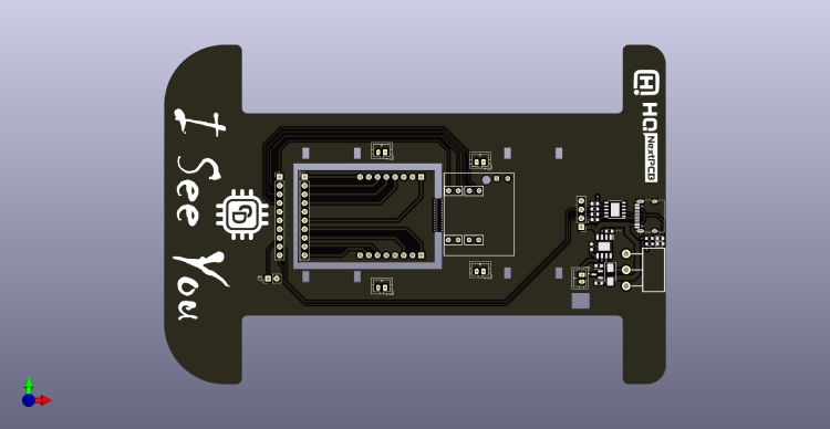
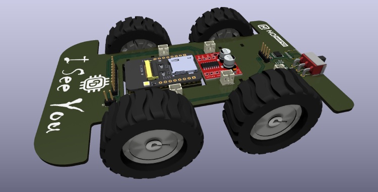
Custom PCB Design

We provide custom PCB design files for easy replication and modification. You can order the PCB from a manufacturer like NextPCB.


Assembly Process

Follow simple steps for assembly, including soldering components, integrating modules, setting up motors and battery, and testing connections.


Programming the Surveillance Car

Set up the Arduino IDE, install ESP32 core and required libraries, customize the code with your WiFi credentials, upload it to the ESP32 Cam module, and start controlling the car remotely through a web interface!


Building this ESP32 Cam Surveillance Car is not just a project—it's an exciting journey into IoT and remote control systems. Whether you're a beginner or enthusiast, this project will surely expand your skills and knowledge in ESP32 development.