Showing posts with label Interfacing. Show all posts

Friday, 20 March 2026

Learn Interfacing Raspberry Pi Pico RTC Module Step-by-Step

Interfacing Raspberry Pi Pico RTC DS3231

If you’ve ever built a digital clock using a microcontroller, you probably noticed one big problem — it loses time when power is removed. That’s exactly where a Real-Time Clock (RTC) module comes in.

In this project, we’re building a reliable digital clock using the Raspberry Pi Pico RTC DS3231 Module, along with a 16x2 I²C LCD to display time, date, and even temperature.

But this isn’t just a simple clock. It’s a solid foundation for future projects like alarms, schedulers, or automation systems.

Why Use the DS3231 RTC?

DS3231 Pinout

Not all RTC modules are equal. Older ones like the DS1307 tend to drift over time, especially with temperature changes. The DS3231 solves this problem with a built-in temperature-compensated crystal oscillator (TCXO).

What does that mean in simple terms?
It automatically adjusts itself based on temperature, so your clock stays accurate whether it’s hot or cold.

Another great feature is the backup battery support. Even if your Pico loses power, the RTC keeps running. So when power comes back, your time is still correct — no resetting needed.

What This Project Does

This setup uses:

  • Raspberry Pi Pico as the controller
  • DS3231 RTC module for accurate timekeeping
  • 16x2 I²C LCD for display

The system shows:

  • Current time
  • Date
  • Temperature (from the RTC module itself)

Since the LCD is small, the code smartly switches between different information instead of showing everything at once.

How It Works

DS3231 RTC Module Schematic

The entire system runs on I²C communication, which is one of the simplest ways to connect multiple devices.

Both the RTC module and LCD share the same two wires:

  • SDA (data)
  • SCL (clock)

The Pico reads time and temperature from the DS3231 and updates the LCD every second.

The best part?
Once you set the time initially, the RTC handles everything on its own.

Setting the Time (Important Step)

There are two easy ways to set the time:

  • Auto method (recommended):
    The RTC takes the current time from your computer during code upload.
  • Manual method:
    You can set a custom date and time directly in the code.

Just remember - after setting the time once, disable that line. Otherwise, it will reset every time the board restarts.

Real-World Uses

This project may look simple, but it’s actually very powerful.

You can use it for:

  • Alarm systems
  • Scheduled automation (like turning lights ON/OFF)
  • Data logging with timestamps
  • Timers and reminders

Once you understand this, you can build much bigger systems.

Common Issues (Quick Tips)

If something doesn’t work, check these first:

  • RTC not working → Battery might be missing or dead
  • LCD showing weird text → Wrong I²C address (try 0x27 or 0x3F)
  • No output → Check SDA and SCL connections

Most problems come down to wiring or small configuration mistakes.

This project is more than just a clock. It teaches you how to:

  • Work with I²C communication
  • Use RTC modules properly
  • Display real-time data on LCD

And once you’ve built this, you’ve got a strong base for more advanced projects.

Simple build. Practical use. And honestly — a great project to level up your embedded skills.

Interfacing Raspberry Pi Pico RTC DS3231 : Easy Setup Guide & Code

https://circuitdigest.com 

Robotics Projects |Arduino Projects | Raspberry Pi Projects|

Monday, 2 February 2026

PCA9306 Module with Arduino Uno: Bidirectional I2C Level Shifting Guide

Interfacing PCA9306 Logic Level Shifter with Arduino Uno

The PCA9306 Module with Arduino Uno is a bidirectional logic level translator designed specifically for I²C bus communication. It allows devices operating at different voltage levels - such as 5V microcontrollers and 3.3V sensors - to communicate safely and reliably. Instead of using discrete MOSFET-based level-shifting circuits, the PCA9306 integrates this functionality into a single IC, ensuring consistent signal integrity and a simpler, more reliable hardware design.

This module automatically handles voltage translation in both directions and preserves standard I²C features such as clock stretching, arbitration, and timing accuracy. Since it uses an open-drain architecture, it remains compatible with most I2C devices. Once powered and enabled, the PCA9306 starts working immediately without any software configuration.

What You’ll Learn from This Project

  • Understanding the PCA9306 pinout and working principle
  • How to interface the PCA9306 with Arduino Uno
  • Reading data from a 3.3V I²C sensor using a 5V Arduino
  • Correct wiring practices for reliable I²C communication
  • Common issues and troubleshooting tips for I²C level shifting

Understanding the PCA9306 Level Shifter Module

The PCA9306 manages two separate I2C voltage domains:

  • VREF1 defines the low-voltage side (typically 3.3V)
  • VREF2 defines the high-voltage side (typically 5V)

Each side has its own SDA and SCL pins, allowing seamless bidirectional signal translation. A common ground between both devices is mandatory, as it provides a shared reference point for voltage levels. The EN (Enable) pin must be driven HIGH (usually tied to VREF2) to activate the module.

Most PCA9306 breakout boards include pull-up resistors on the low-voltage side, while the high-voltage side typically relies on the host controller’s pull-ups.

PCA9306 Pin Description

  • VREF1 – Low-voltage reference (3.3V)
  • VREF2 – High-voltage reference (5V)
  • SCL1 / SDA1 – I²C lines for 3.3V devices
  • SCL2 / SDA2 – I²C lines for 5V devices (Arduino A5/A4)
  • GND – Common ground
  • EN – Enable pin (must be HIGH)
PCA9306-Module-Pinout

Components Required

Wiring the PCA9306 with Arduino Uno

PCA9306 Wiring Diagram

To interface a 3.3V BMP180 sensor with a 5V Arduino:

  • Connect VREF1 → 3.3V
  • Connect VREF2 → 5V
  • Connect SDA2 → A4, SCL2 → A5
  • Connect SDA1 / SCL1 → BMP180
  • Tie all GND pins together
  • Pull EN HIGH

Once wired, no special configuration is required for the PCA9306.

Real-World Applications of PCA9306

  • Connecting 3.3V sensors to 5V microcontrollers
  • Interfacing EEPROMs across voltage domains
  • Multi-board embedded systems
  • Backplane or modular I²C designs
  • Legacy hardware integration

In this project, we successfully interfaced the PCA9306 logic level shifter with an Arduino Uno to communicate with a 3.3V BMP180 pressure sensor. By using proper voltage references, correct wiring, and a shared ground, we achieved stable I2C communication without modifying the software.

The PCA9306 proves to be a reliable and efficient solution for bidirectional I²C voltage translation, especially in mixed-voltage embedded systems.

Thursday, 25 December 2025

Interfacing SD Card Module with Raspberry Pi Pico Using SPI


Adding external storage to a microcontroller project opens up many possibilities, from data logging and configuration storage to saving time - stamped sensor readings. The Raspberry Pi Pico SD card module is a simple and reliable way to achieve this using a standard microSD card and the SPI communication protocol.

In this project, we are Raspberry Pi Pico SD card module and demonstrate how to create, read, write, and delete files using an interactive Serial Monitor menu. This setup provides a clear understanding of how embedded systems handle external storage using the FAT32 file system.

Overview of the Project

The Raspberry Pi Pico communicates with the SD card module using the SPI interface. Most SD card modules include a built-in 3.3V regulator and basic level shifting, making them safe to use directly with the Pico’s 3.3V logic levels. Once connected, the Pico can access gigabytes of storage for logging sensor data, storing text files, or saving device settings.

To make the learning experience more interactive, this project uses a Serial Monitor menu that allows users to perform file operations in real time by sending simple commands.

Components Required

  • Raspberry Pi Pico
  • SD card module 
  • microSD card 
  • Breadboard and jumper wires
  • USB cable for power and programming

SD Card Module Pin Configuration for Raspberry Pi Pico

SD Card Module Pin Configuration for Raspberry Pi Pico

How It Works

The SD card module connects to the Pico’s default SPI0 pins. The Arduino SD and SPI libraries handle communication, file creation, reading, writing, and deletion. Once powered on:

  • The Pico initializes the SD card
  • A menu appears on the Serial Monitor
  • Users select actions like creating a file, writing text, reading data, or deleting files
  • All operations are executed instantly and displayed in real time

This makes it easy to understand how SPI communication and file handling work internally.

Circuit Diagram 

Circuit diagram Interfacing SD Card Module with Raspberry Pi Pico


SD Card Preparation Tips

For reliable operation:

  • Format the SD card to FAT32
  • Use a single MBR partition
  • Avoid exFAT or GPT formatting
  • Prefer standard Class 4 or Class 10 microSD cards

Improper formatting is the most common reason for SD card initialization failures.

Applications of Raspberry Pi Pico SD Card Interface

  • Sensor data logging
  • Configuration and settings storage
  • Offline data recording
  • IoT and embedded monitoring systems
  • Long-term data collection projects
for further in-depth details : Raspberry Pi Pico SD card module

Sunday, 7 April 2024

Troubleshooting Guide: Interfacing SIM800L with Arduino

If you've ever worked with the SIM800L module (Arduino GSM), you know it's a versatile tool for a variety of projects, from making calls to sending SMS and accessing the internet via GPRS. However, like any tech, it has its quirks. In this article, we'll guide you through interfacing the SIM800L with Arduino and offer troubleshooting tips to ensure smooth operation. Plus, we'll touch on our experience with the SIM800L on ESP32 if you're curious.


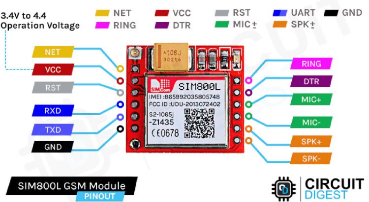
Understanding SIM800L Module Pinout:

The SIM800L module, a GSM/GPRS module, features various pins serving distinct functions critical for its operation. Among these pins, VCC provides the power supply, while GND serves as the ground connection. TX and RX facilitate data transmission and reception, enabling communication with other devices. Understanding the pinout is essential for correctly connecting the module to other components in the system.


Powering the SIM800L GSM Module:

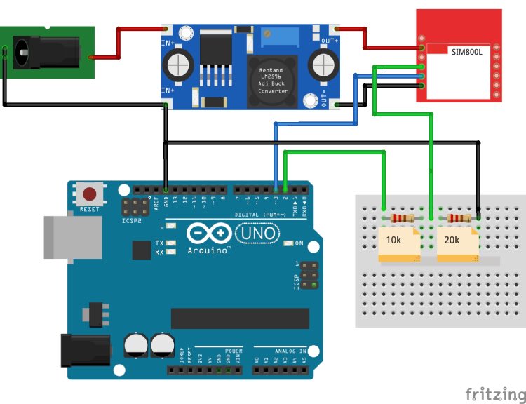
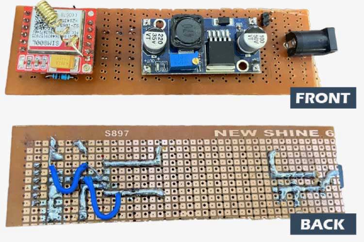
Powering the SIM800L module requires a stable power supply within the range of 3.7V to 4.2V. Achieving this can be accomplished using a buck converter with a minimum current capacity of 2A or a 3.7V Li-ion battery. Additionally, adding a capacitor between VCC and GND can enhance power stability, although it's not mandatory for basic functionality.


Interfacing SIM800L with Arduino UNO:

Interfacing the SIM800L with an Arduino UNO necessitates addressing voltage compatibility issues. While the SIM800L operates at 3.3V, the Arduino UNO internally operates at 5V. To bridge this voltage discrepancy safely, a voltage divider calculator is typically employed, utilizing resistors to generate a 3.3V signal from the Arduino's 5V output.


Troubleshooting SIM800L Issues:

Common issues encountered with the SIM800L module include challenges with SIM card detection and network connectivity. The LED indicators on the module offer valuable insights, such as network status, aiding in the troubleshooting process. Steps for troubleshooting involve verifying correct SIM card insertion, ensuring a stable power supply, and checking for adequate network coverage.


SIM800L AT Command Testing:

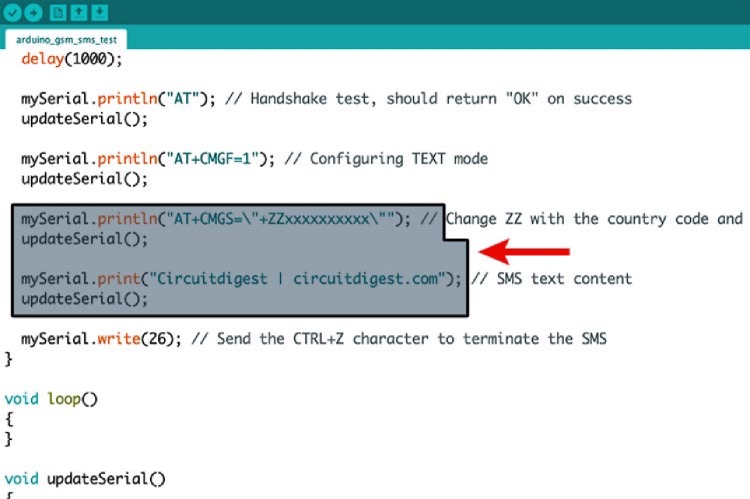
AT commands are instrumental in communicating with the SIM800L module and executing various functions. By uploading an SIM800L AT command test program to the Arduino, direct communication with the module is established. Sending AT commands and interpreting the responses allows for the verification of the module's responsiveness and functionality.


Sending SMS and Making Calls:

Upon confirming the responsiveness of the SIM800L module, exploring its features such as sending SMS and making calls becomes feasible. Sample Arduino code is available for executing these actions, accompanied by detailed explanations of each step in the process. These functionalities broaden the scope of potential applications, enabling communication capabilities within projects.


Conclusion:

Mastering the intricacies of the SIM800L module empowers individuals to leverage its capabilities effectively in various projects. Understanding the module's pinout, power requirements, and troubleshooting techniques facilitates overcoming challenges that may arise during implementation. Furthermore, exploring additional projects, such as SMS-based vehicle tracking and forest fire warning systems, fosters ongoing learning and innovation in utilizing the SIM800L module.


Tuesday, 7 July 2015

Interfacing 7 segment display module with 8051 Microcontroller

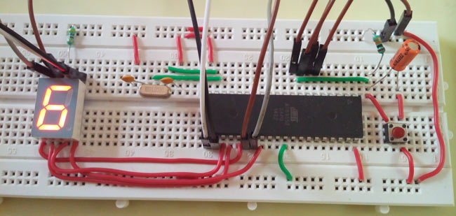
Once you get started with 8051 microcontroller and do some initial experiments like LED Interfacing, you would like to move ahead with interfacing some commonly used sensors and display units like LCDs and 7 segment displays. Let us see a tutorial which will share the details of 7 segment displays, their working and a detailed guide to interface with 8051 microcontroller.


Seven segment displays are among the simplest display units to display numbers and some characters. It consists 8 LEDs, each LED used to illuminate one segment of unit and the 8th LED used to illuminate DOT in 7 segment display. We can refer each segment as a LINE, as we can see there are 7 lines in the unit, which are used to display a number/character.

Check out the circuit diagram and C program to interface 7 segment display with 8051 microcontroller.

Here is the video which depicts a 0-9 number counter on the 7 segment.


Monday, 22 June 2015

Interfacing LED with 8051 Microcontroller

LED Interfacing program is the first program you would like to write while getting started working with 8051 series or any other microcontrollers. Here is a tutorial for those who want to learn 8051 microcontroller programming - Tutorial on LED Interfacing with 8051 Microcontroller


Here basic concepts of working with 8051 microcontrollers are covered with pin diagrams of 89S52 microcontroller and their role in the microcontroller. 

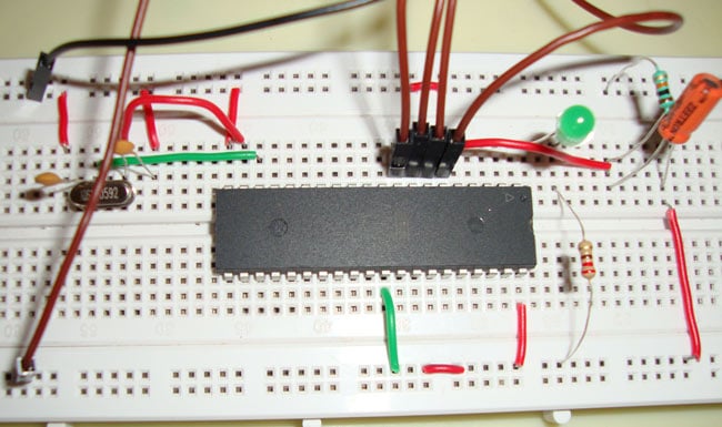
Check this complete tutorial and try your hands on this small experiment by writing a simple C program to blink an LED.