Showing posts with label DIYElectronics. Show all posts

Tuesday, 24 March 2026

Simple Optocoupler Tester Circuit for Quick and Reliable Testing

Optocouplers are small but critical components used in many electronic circuits for isolation and signal transfer. The tricky part? When they fail, they usually don’t show any visible signs. Everything looks fine on the outside, but internally, either the LED or the phototransistor might stop working.

That’s where a simple optocoupler tester circuit becomes extremely useful. Instead of guessing or relying only on a multimeter, this small tester gives you clear results in seconds.

What This Tester Does

This optocoupler tester is designed to quickly check whether an optocoupler is working properly or not. It verifies two key things:

  • Whether the internal LED (input side) is functioning
  • Whether the output side responds to the light

The circuit is simple, battery-powered, and doesn’t require any measuring tools. It’s perfect for lab use, repair work, or even checking salvaged components.

How the Circuit Works


The working principle is based on optical isolation.

When you press the push button:

  • Current flows through the internal LED of the optocoupler
  • A red LED glows, indicating the input side is active
  • The emitted light triggers the output transistor
  • A green LED turns ON if the output side is working

So, in just one press, you get a complete functional check.

The results are easy to understand:

  • Both LEDs ON → Optocoupler is good
  • Only red LED ON → Output side is faulty
  • No LEDs ON → Input LED or connection issue
  • Green LED only → Possible wiring error or short

This makes troubleshooting fast and beginner-friendly.

Components Used

The best part of this project is how simple it is.

You only need:

  • Optocoupler (for testing)
  • Red LED (input indication)
  • Green LED (output indication)
  • Push button
  • 3.7V Li-ion battery
  • Two 470Ω resistors
  • IC sockets (4-pin & 6-pin)
  • Dot board

Using IC bases is a smart choice here. It lets you test multiple optocouplers without soldering or risking heat damage.

Why Not Just Use a Multimeter?

You can test an optocoupler using a multimeter, but it has limitations.

A multimeter:

  • Can check only the input LED properly
  • Cannot fully verify the output response
  • Requires manual probing and interpretation

This tester, on the other hand:

  • Checks both input and output together
  • Gives instant visual results
  • Takes less than 2 seconds per test

So for regular use, a dedicated tester is much more practical.

Where This Is Useful

This simple circuit is surprisingly helpful in many situations:

  • Electronics labs
  • Repair and maintenance work
  • Testing bulk components
  • Educational projects
  • Verifying reused or salvaged parts

It saves time and prevents faulty components from being used in circuits.

This Optocoupler Tester Circuit is a perfect example of a small project that solves a real problem. It’s simple, low-cost, and extremely practical.

Instead of spending time guessing or troubleshooting blindly, you get a clear pass/fail result instantly. And once you build it, you’ll find yourself using it again and again.

If you’re working with optocouplers regularly, this is definitely a must-have tool on your workbench.

https://circuitdigest.com 

Robotics Projects |Arduino Projects | Raspberry Pi Projects|

Friday, 9 January 2026

DIY Bluetooth Speaker — Build Your Own Wireless Audio System

diy bluetooth speaker amplifier

Listening to music wirelessly through a Bluetooth speaker is something we all enjoy, but did you know you can build your own DIY Bluetooth Speaker Amplifier at home with just a few affordable electronic parts? This DIY Bluetooth speaker project lets you stream music from your phone or any Bluetooth-enabled device without wires. It’s a fun and practical way to learn about wireless audio, amplification, and basic circuitry while creating a portable speaker you can actually use.

What This Project Is About

In this project, you’ll combine a Bluetooth audio receiver module with a small audio amplifier and speaker drivers to make a compact and budget-friendly wireless speaker system. The Bluetooth module receives audio wirelessly, the amplifier boosts the signal to drive the speakers, and everything runs on a simple power supply like a USB power bank or 5 V adapter.

Components Required

To build your Bluetooth speaker, you’ll need:

  • JDY-62 Bluetooth 4.2 module – Receives audio over Bluetooth
  • PAM8403 amplifier board – Boosts audio signal to drive speakers
  • 2 × 8Ω speakers – Produce sound output
  • 5 V power supply – USB power bank or wall adapter
  • Wires and soldering tools – For connections and assembly
Components Required diy bluetooth speaker amplifier

Components Required diy bluetooth speaker amplifier

These parts are inexpensive and widely available, making this project easy for beginners and hobbyists alike.

How It Works

  1. Bluetooth Audio Reception – The Bluetooth module pairs with your phone or tablet and receives the audio signal wirelessly.
  2. Signal Amplification – The audio output from the Bluetooth module is fed into the PAM8403 amplifier, which boosts the low-level audio signal.
  3. Speaker Output – Amplified audio drives the connected speakers to produce clear sound.
  4. Power Supply – A simple 5 V source powers both the Bluetooth module and amplifier, keeping the system compact and portable.
DIY Bluetooth Speaker Circuit Diagram

When you turn on the system and pair your device, you’ll be ready to enjoy wireless audio instantly.

Why This Project Is Great

  • Affordable and practical - Easy to build for under a small budget.
  • Wireless music - Stream audio from phones and laptops seamlessly.
  • Educational - Learn about Bluetooth modules, audio amplification, and basic electronics.
  • Customisable - Expand with volume controls, battery power, or LED indicators.

Building your own DIY Bluetooth Speaker Amplifier is both fun and rewarding. With just a Bluetooth audio receiver, a tiny amplifier, and a pair of speakers, you can create a wireless audio system that works anywhere. It’s a perfect weekend project for beginners and a great way to dive into practical electronics while enjoying music in style. 

Tuesday, 11 March 2025

How to Build a Bidirectional Visitor Counter using Arduino

How-to-Build-a-Bidirectional-Counter-Using-Arduino-and-IR-Sensors
What is a Bidirectional Counter?

A bidirectional counter counts objects or people moving in two directions, incrementing the count for one direction and decrementing for the opposite. It is commonly used in:

  • Automatic door entry systems
  • Visitor counters in malls, offices, and stations
  • Industrial conveyor belt monitoring

Components Required

To build this project, you'll need:

  • Arduino Uno
  • IR Sensors (2x)
  • 7-Segment Display or LCD
  • Resistors & Capacitors
  • Jumper Wires & Breadboard
Hardware-Connection-of-Bidirectional-Counter-System-using-IR-Sensors (1)


This project demonstrates how to use the L298N Motor Driver Module with Arduino to control the speed and direction of a DC motor. By leveraging PWM (Pulse Width Modulation) signals, you can achieve precise motion control, making it ideal for robotics, automation, and motorized systems. Whether you're a beginner or an advanced maker, this tutorial will help you understand motor control concepts and apply them to your own projects.

Wednesday, 22 May 2024

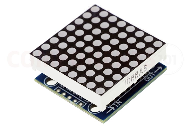
A Beginner's Guide to the MAX7219 8x8 LED Matrix Module

 The MAX7219 8x8 LED matrix module is a small but mighty display tool loved by hobbyists and tech enthusiasts alike. Let's break down what makes this module so cool and how you can use it in your own projects.


What is the MAX7219 LED Matrix Module?

The MAX7219 LED matrix module is a neat little gadget that makes it easy to control lots of LEDs at once. With it, you can light up to 64 individual LEDs in a grid pattern, showing characters, symbols, or even animations.


What Makes it Special?

  • Easy to Use: It's designed to be simple to connect and control, so you can focus on being creative.

  • Tiny but Powerful: Despite its small size, it can handle a lot of LEDs, giving you plenty of room to play.

  • Works with Many Devices: Whether you're using an Arduino, Raspberry Pi, or something else, chances are this module will play nicely with it.


How Do You Use It?

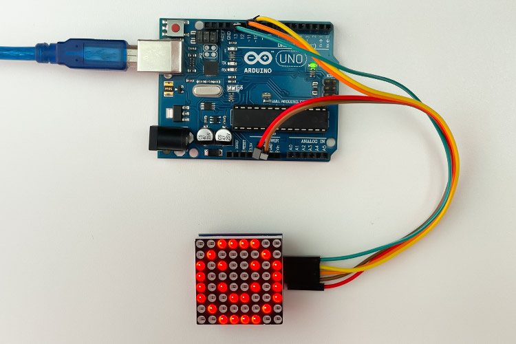
Connecting the MAX7219 module to your device is a piece of cake. Just hook up a few wires, and you're good to go. From there, you can start programming it to display whatever you want – the only limit is your imagination!


Tips for Troubleshooting

If things aren't going smoothly, don't panic! Here are a few things to check:


  • Power Supply: Make sure you're giving it enough juice – it likes to run on 5 volts.

  • Brightness: If the display looks dim or flickery, try adjusting the brightness settings.

  • Double-Check Connections: Sometimes, a loose wire is all that's standing between you and success.


What Can You Do with It?

The possibilities are endless! Use it to make your own DIY projects, create eye-catching signs, or even build interactive displays. Whether you're a seasoned pro or just getting started, the MAX7219 LED matrix module is sure to spark your creativity.


The MAX7219 LED matrix module may be small, but it's mighty. With its simple setup, compatibility with popular devices, and endless potential for creativity, it's the perfect tool for bringing your ideas to life. So what are you waiting for? Get out there and start making something amazing!


Full Video Tutorial : https://youtu.be/pHw3AokxRXM


Monday, 20 May 2024

Easy Steps to Interface OLED Display With Arduino


Are you tired of the limitations posed by traditional LCD displays in your Arduino projects? Say hello to Arduino OLED displays – the versatile, feature-rich alternative that opens up a world of possibilities for your creations. In this comprehensive guide, we'll delve into everything you need to know about OLED displays and how to seamlessly integrate them with your Arduino projects.


Understanding OLED Displays

OLED (Organic Light Emitting Diode) displays are a game-changer in the realm of visual interfaces. Unlike LCD technology, OLED displays are self-emissive, meaning each individual pixel generates its own light, eliminating the need for a backlight. This not only results in deeper blacks and vibrant colors but also enables thinner and more energy-efficient displays.


Types of OLED Displays

OLED displays come in various sizes, resolutions, and communication protocols, offering flexibility to suit diverse project requirements. The two primary communication protocols used are I2C and SPI, each with its own advantages in terms of speed and complexity.


I2C OLED Display Module Pinout:


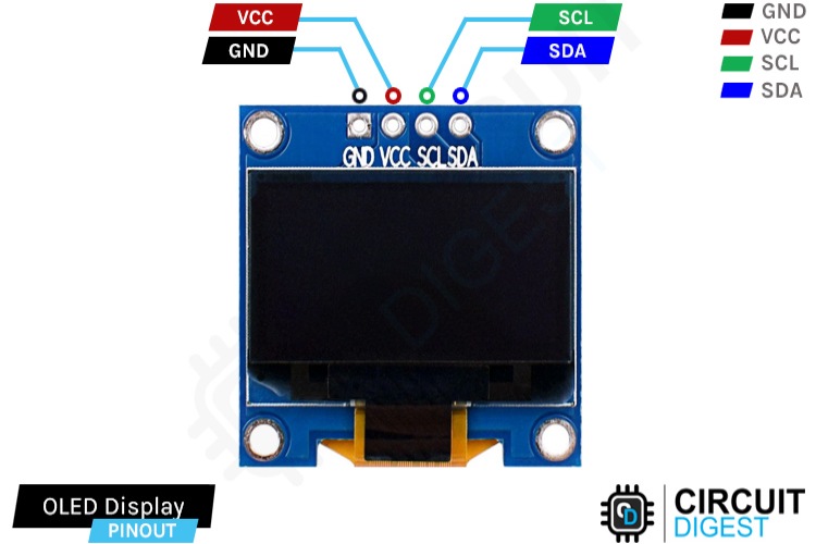
Ground (GND): Connect to the Arduino's ground pin.

Power (VCC): Provides power to the module (usually connected to the 5V pin).

Serial Clock (SCL): Generates clock pulses for I2C communication.

Serial Data (SDA): Transfers data via I2C communication.


SPI OLED Display Module Pinout:


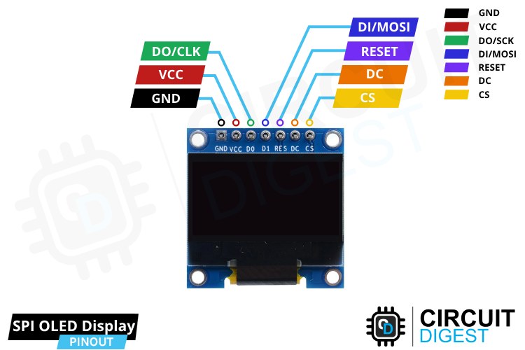
Ground (GND): Connect to the Arduino's ground pin.

Power (VCC): Provides power to the module (usually connected to the 5V pin).

Serial Clock (D0/CLK): Generates clock pulses for SPI communication.

Serial Data In (D1/MOSI): Sends data to the display.

Reset (RESET): Resets the internal buffer of the display.

Data/Command (DC): Controls the type of data sent to the display.

Chip Select (CS): Selects the display controller.


Interfacing with Arduino

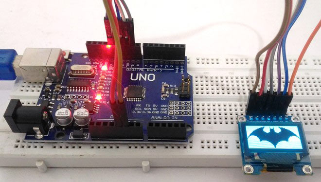
Connecting OLED displays to Arduino boards is straightforward, requiring minimal components and simple wiring. Whether using I2C or SPI interface, the process involves connecting power, ground, and communication pins according to the chosen protocol.


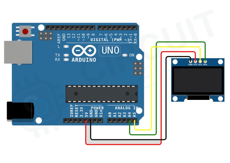
I2C OLED Module Interfacing Connection Diagram:


GND to GND pin

VCC to 5V pin

SCL to A5 pin

SDA to A4 pin


SPI OLED Module Interfacing Connection Diagram:


GND to GND pin

VCC to 5V pin

D0/CLK to digital pin 10

D1/MOSI to digital pin 9

RESET to digital pin 13

DC to digital pin 11

CS to digital pin 12


Programming OLED Displays

Once the hardware connections are established, programming OLED displays with Arduino involves installing the necessary libraries and writing code to control the display content. Whether using I2C or SPI, the Adafruit SSD1306 and Adafruit GFX libraries are essential for interfacing with OLED displays.


Basic Text and Graphics Functions

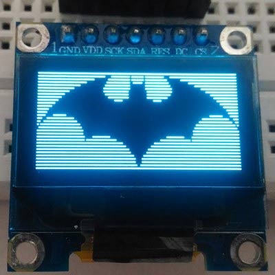
From displaying text and numbers to drawing shapes and images, OLED displays offer a myriad of possibilities for visual representation. Using functions provided by the Adafruit GFX library, you can manipulate text size, color, and position, as well as draw various shapes with ease.


Troubleshooting and Common Issues

While working with OLED displays, encountering issues is not uncommon. However, by following a systematic troubleshooting approach, you can quickly identify and resolve common problems related to hardware connections, power supply, code errors, and display settings.


In conclusion, OLED displays present a versatile and powerful solution for visual interfaces in Arduino projects. By understanding the different types of OLED displays, mastering their interfacing with Arduino, and leveraging the rich set of programming functions, you can unlock endless possibilities for creativity and innovation in your projects.


Check out our comprehensive video tutorial on integrating OLED displays with Arduino


Sunday, 12 May 2024

Advanced Arduino Project Exploration for Engineering Students

Are you an engineering student keen on practical electronics and embedded systems? Let's delve into a range of fascinating Arduino projects that will boost your skills and understanding of microcontroller applications.


1. DIY Arduino Bluetooth Car Controlled by Mobile Application

Have you ever wanted to create your own remote-controlled robot car? This project will teach you how to build a Bluetooth-controlled car that you can maneuver wirelessly using a mobile app. It's a fantastic gateway into the world of remote-controlled robotics and IoT.


2. Interfacing Seven Segment Display with Arduino

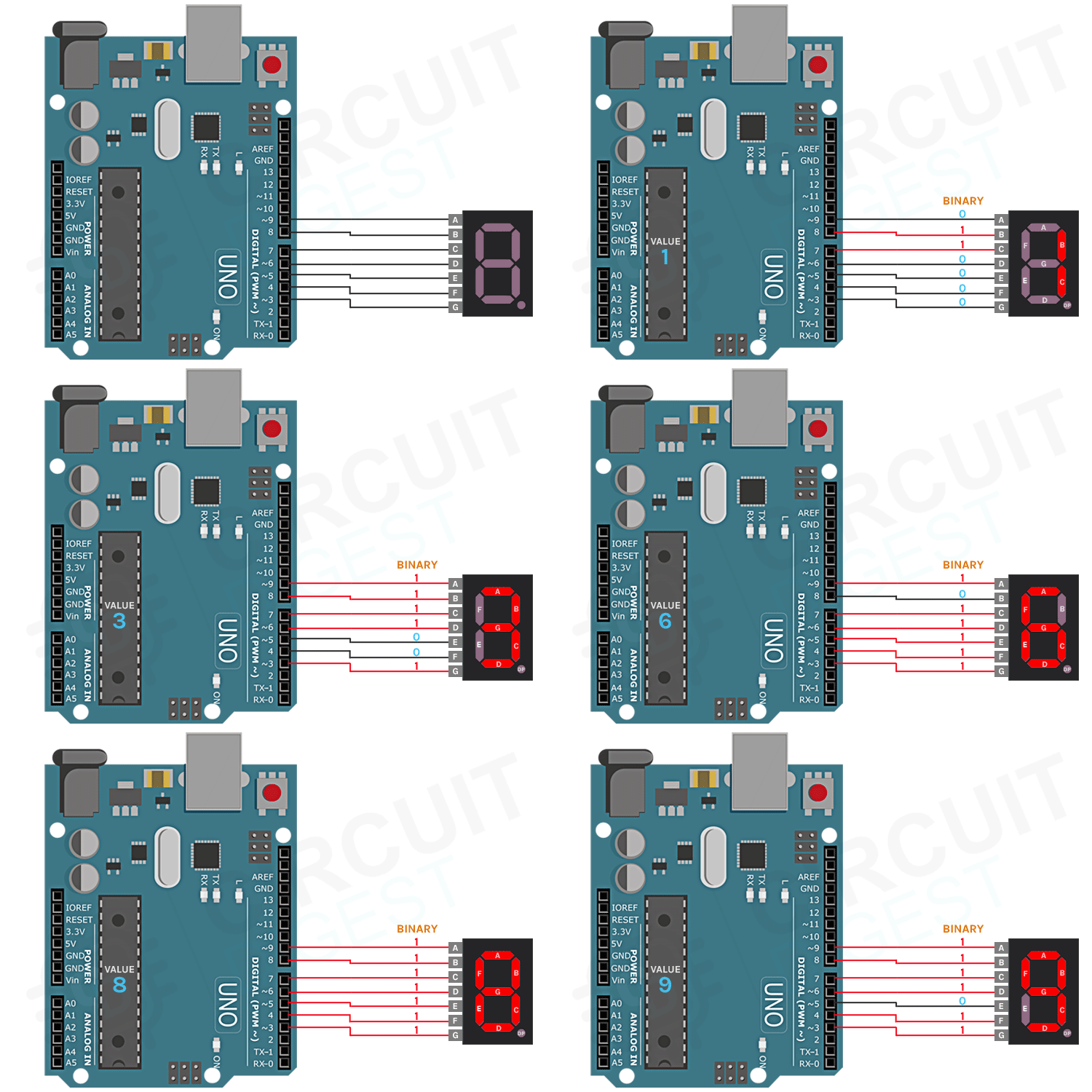
If you're new to electronics, learning how to connect and control a seven-segment display with Arduino is a great starting point. This project lays the foundation for understanding basic electronics and display technologies, which are useful in a wide range of digital applications.


3. Building your own Sun Tracking Solar Panel using an Arduino

Imagine a solar panel that automatically adjusts its position to maximize sunlight exposure throughout the day. With Arduino, you can create your own sun-tracking system that optimizes solar energy efficiency. It's a fascinating project for renewable energy enthusiasts.


4. Programming ESP32 using Arduino Labs for MicroPython

Looking to delve into MicroPython programming with the powerful ESP32 microcontroller? This project combines the versatility of ESP32 with the simplicity of MicroPython, making it ideal for various IoT and wireless communication applications.


5. Arduino-based Hourglass using Accelerometer and LED Matrix Displays

Transform the concept of a traditional hourglass into a modern marvel using Arduino, accelerometer sensors, and LED matrix displays. This unique project showcases the creative integration of sensors and visual displays in timekeeping devices.


6. DIY Motorized Solder Paste Dispenser for Automatic Solder Paste Application

Streamline your soldering tasks with a DIY motorized solder paste dispenser powered by an ATmega328 microcontroller. This project is essential for electronics enthusiasts engaged in manufacturing and prototyping.


7. Build a Battery Internal Resistance Meter with Arduino and Atmel ATtiny85 IC

Ensure optimal performance and longevity of batteries with a homemade internal resistance meter using Arduino and Atmel ATtiny85 IC. It's a handy tool for testing and maintaining batteries in portable electronic devices.


8. DIY Digital Distance Measuring Wheel using Rotary Encoder

Create your own digital distance measuring wheel using Arduino and a rotary encoder. This project is perfect for applications requiring precise distance measurements in robotics, surveying, or DIY projects.


9. Laser Engraving with DIY Arduino SCARA Robot

Explore the art of laser engraving by building a SCARA (Selective Compliance Assembly Robot Arm) robot powered by Arduino. This project merges precision robotics with laser technology, offering advanced prototyping possibilities.


10. Earthquake Indicator Using Arduino

Develop an earthquake indicator system using Arduino for real-time monitoring and detection of seismic activities. This project is invaluable for disaster preparedness and showcases Arduino's versatility in sensor applications.


These Arduino projects offer a comprehensive exploration of electronics, robotics, and IoT applications. Whether you're a beginner or an experienced engineer, each project provides valuable hands-on experience and opens doors to endless possibilities in the world of embedded systems and automation.


Get ready to unleash your creativity and engineering skills with these fascinating Arduino projects!


Monday, 1 April 2024

How to Build a Low-Cost Drone with ESP32?


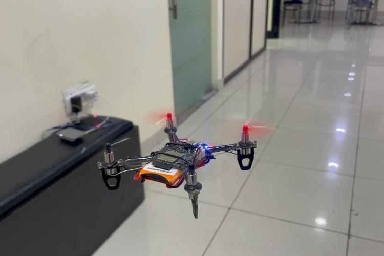
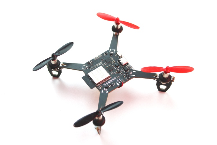
Drones have evolved from simple toys to versatile tools with countless applications across industries. Whether for aerial photography, agricultural monitoring, or military operations, drones rely on advanced technology for their functionality. In this project, we'll create a DIY Wi-Fi Controlled Drone using accessible components like ESP32 modules, MPU6050 IMU, coreless motors, and plastic propellers. This method enables hobbyists to build their own drones without requiring costly equipment.


Key Features:


  • Smartphone Control: Operate the drone wirelessly via smartphone for easy handling.

  • Stability Control: Integrated MPU6050 IMU ensures smooth flight performance.

  • Compact Design: All-in-one PCB layout simplifies assembly, eliminating the need for 3D printed parts.

  • Upgradability: Easily integrate additional features for customization in the future.

  • Lightweight: Portable and maneuverable design makes it ideal for various applications.

  • Built-in Convenience: Includes features like built-in battery charging and USB interface for programming and debugging.

  • Compatibility: Works seamlessly with both Android and iOS devices.

  • Open-Source: Customize and modify the drone to suit individual preferences.


Components Needed:

For this project, gather:


  • ESP32 modules

  • MPU6050 IMU

  • Coreless motors

  • Propellers

  • PCBs

  • Other electronic components

Check the provided list for a comprehensive overview.


1) Our circuit diagram showcases connections between components, including USB port for charging and programming, voltage regulation, and motor driver circuits.


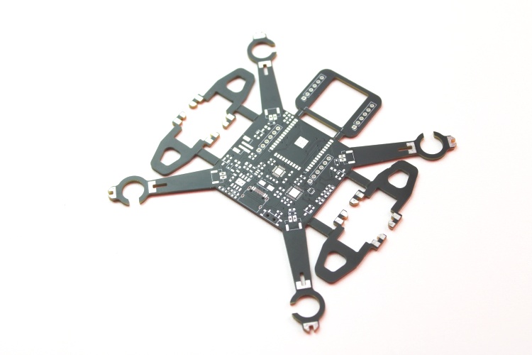
2) Compact and sturdy PCB design ensures easy assembly and incorporates mounting feet for stability.


3) The drone's firmware, based on ESP-drone firmware from Espressif, is coded using ESP-IDF version 4.4.5. It controls user commands, sensor data processing, and motor control.


4) Pre-flight checks are essential to ensure proper functionality before takeoff.


Supporting Files:

Download schematics, PCB designs, and firmware from the Circuit Digest GitHub repository.

For a detailed tutorial, watch the complete video guide here.