Showing posts with label electronics. Show all posts

Wednesday, 4 March 2026

Reverse Polarity Protection Using MOSFET: Guard Your Circuit the Smart Way

Reverse Polarity Protection Using P-Channel Mosfet

You've just finished assembling an electronics project and you're ready to power it up - only to realize the battery might be connected backwards. In that single instant, hours of careful work can be destroyed. Reverse polarity is one of the most common causes of circuit failure, and without protection, it causes immediate component damage, permanent IC failure, or worse, thermal runaway. The good news is that a Reverse Polarity Protection Circuit Using MOSFET can prevent all of that with near-zero efficiency penalty.

Why a Diode Alone Isn't Enough

Diode Based Reverse Polarity Protection Circuit Diagram

The classic fix is simple: place a diode in series with the positive rail. When polarity is correct, it conducts. When reversed, it blocks. It works - but it comes with a hidden cost.

Every forward-biased diode drops approximately 0.7 V and converts that energy directly into heat. In a 12 V system drawing 500 mA, that's 0.35 W of continuous loss and a 5.8% voltage penalty - every second the circuit is powered. For battery-operated or low-voltage devices, that's a tax you simply cannot afford.

The MOSFET Solution

A P-channel MOSFET placed in series with the positive supply line solves the same problem at a fraction of the cost. Here's why it works so elegantly.

When the supply is connected correctly, the gate is pulled to ground through a resistor while the source sits at supply voltage. This makes VGS negative, which turns the MOSFET fully ON - conducting through a channel resistance as low as 0.1 Ω. When polarity is reversed, VGS becomes positive, the MOSFET switches OFF, and current is completely blocked. The internal body diode, oriented against reverse current, provides an additional safety layer.

Running the same numbers - 12 V, 500 mA, RDS(on) of 0.1 Ω - the voltage drop is just 0.05 V and power loss is only 0.025 W. That's a 0.4% efficiency impact compared to the diode's 5.8%. The MOSFET dissipates roughly 14 times less power under identical conditions.

How to Build It

You need just four components: a P-channel MOSFET (IRF9710), a 1N4007 diode, a 1 kΩ gate resistor, and your load.

Place the IRF9710 on a breadboard and identify the Source, Gate, and Drain from the datasheet. Connect the 1 kΩ resistor from Gate to Ground - this pull-down keeps VGS negative under correct polarity. Add the 1N4007 with cathode to Gate and anode to Ground to prevent a damaging reverse gate voltage from appearing during a miswiring event. Finally, connect your load between the Drain rail and GND. Correct polarity powers the load normally. Reversed polarity keeps the MOSFET off and the load completely unharmed.

When to Add a Zener Diode

MOSFET Reverse Polarity Protection with Gate Zener

The basic circuit works well below 20 V. For automotive systems, industrial rails, or any environment with voltage spikes, the gate-to-source voltage can momentarily exceed the MOSFET's ±20 V rating and permanently damage the gate oxide - often with no visible warning.

Adding a Zener diode between Gate and Source clamps VGS to a safe level. It's one extra component, costs almost nothing, and is the difference between a circuit that survives field conditions and one that doesn't.

Choosing the Right MOSFET

P Channel MOSFET Reverse Polarity Protection Circuit Diagram

Five parameters matter when selecting a device. VDS(max) should be at least 1.5 times your supply voltage. VGS(th) must be low enough to switch on fully at your rail - for 3.3 V or 5 V systems, use a logic-level device like the AO3401. RDS(on) should be below 0.1 Ω for currents under 5 A. ID(max) should be at least twice your peak load current. And if your supply exceeds 15 V, include the Zener gate clamp.

A diode protects your circuit but wastes energy doing it. A P-channel MOSFET protects your circuit while barely touching efficiency. For battery-powered gadgets, microcontroller boards, IoT sensors, automotive accessories, or any project where efficiency and reliability both matter, MOSFET-based reverse polarity protection is the right engineering choice - and it costs almost nothing to implement correctly.

For more in depth understanding : Reverse Polarity Protection Using MOSFET | Step By Step Circuit Guide


https://circuitdigest.com 

Robotics Projects |Arduino Projects | Raspberry Pi Projects|

Tuesday, 24 February 2026

Arduino Robotic Arm with 6 DOF

DIY Arduino Robotic Arm

We have build a Robotic Arm using Arduino Nano, an interactive robotics system that translates human hand movements into real-time robotic motion. This Arduino Robotic Arm is for engineering students who want practical exposure to embedded systems, sensors, and real-time control.

Components Used

  • Arduino UNO
  • 3 × MG995 High-Torque Servo Motors
  • 3 × Micro Servo Motors
  • Breadboard
  • Jumper Wires
  • 3D Printed Parts
  • Screws & Assembly Hardware
  • External 5V Power Supply
Components Required for Arduino Robotic Arm
DIY Arduino Robotic Arm Components

Robotic Arm Fundamentals

Robotic Arm Joints

Joints allow bending and rotation, similar to human elbows and wrists. In a 6-axis arm, six joints work together to achieve complex 3D positioning.

Degrees of Freedom (DOF)

DOF represents independent movements.

  • 1 DOF → One direction movement
  • 3 DOF → Basic 3D movement
  • 6 DOF → Human-like flexibility

Servo Motor Control

Servo motors rotate to specific angles (0°–180°) using PWM signals. Proper torque selection is important for lifting weight safely.

Power Management

Multiple servos require an external 5V power supply. USB power from Arduino is not sufficient.

3D Design & Printing

The robotic arm structure is fabricated using 3D printing for lightweight and easy assembly.

Real-World Applications

Although this project appears simple, its core concept is widely used in advanced systems -
  • Industrial robotic manipulators
  • Remote-controlled robotic systems
  • Prosthetic hand control systems
  • Hazardous material handling robots
  • Surgical robotic systems

The Arduino Robotic Arm using Arduino UNO is more than a DIY robotics build - it’s a stepping stone into real-world automation and intelligent systems.

If you're serious about robotics, automation, or mechatronics, this is exactly the kind of project that strengthens your fundamentals while staying exciting and hands-on.

https://circuitdigest.com 

Robotics Projects |Arduino Projects | Raspberry Pi Projects|

Wednesday, 5 June 2024

Explore the fundamentals of Full Adder circuits


Binary adders come in two types: Half Adders and Full Adders. A half adder adds 2-bit binary numbers but cannot include a carry bit. In contrast, a Full Adder adds the carry bit along with the two binary numbers, enabling the addition of multi-bit binary numbers by cascading multiple Full Adder circuits.


Full Adder Circuit

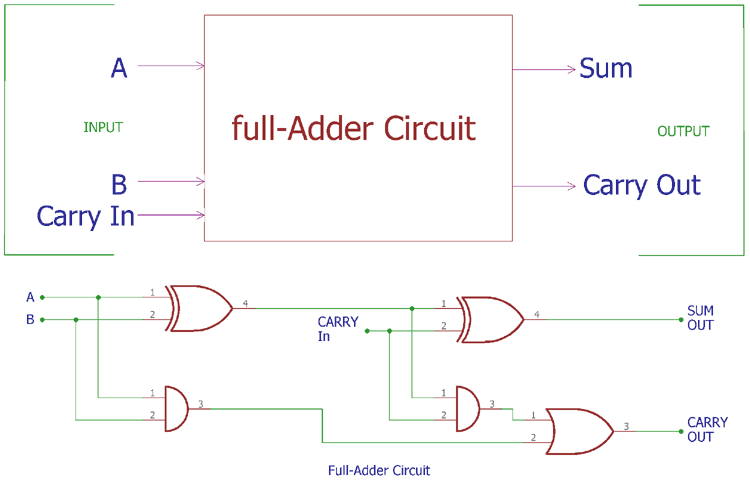
The main limitation of a half adder is the lack of a ‘Carry in’ bit. In a Full Adder circuit, we include a carry in input and add it to inputs A and B, giving us three inputs (A, B, and Carry In) and producing two outputs (SUM and Carry Out).


Full Adder Block Diagram

The Full Adder is constructed by combining two half-adder circuits and an OR gate. Here’s how it works:


  1. The first half-adder adds inputs A and B, producing SUM and Carry out.

  2. The SUM output from the first half-adder is fed into the second half-adder along with the Carry in bit.

  3. The final SUM output is the result of the Full Adder.

  4. The Carry out bits from both half-adders are combined using an OR gate to produce the final Carry out.


Construction of Full Adder Circuit

Here’s a step-by-step guide to constructing a Full Adder Circuit:


Components Needed

  • Two Half Adder circuits

  • OR Gate

  • Steps

  • Connect the inputs A and B to the first half-adder.

The SUM output from the first half-adder goes to the input of the second half-adder along with the Carry in bit.

The final SUM output from the second half-adder is the overall SUM output of the Full Adder.

Combine the Carry out bits from both half-adders using an OR gate to produce the final Carry out.


Circuit Diagram and Logic Gates

The full adder circuit utilizes XOR, AND, and OR gates. The two half adders are connected such that the first half adder handles inputs A and B, while its SUM output and the Carry in bit are fed into the second half adder. The OR gate then combines the Carry out bits from both half adders.


Truth Table of Full Adder Circuit

The truth table for the Full Adder circuit includes three inputs (A, B, Carry In) and two outputs (SUM, Carry Out):


The SUM output is obtained by XORing inputs A and B and then XORing the result with the Carry in bit. The Carry out is calculated by ORing the AND results of the input pairs.


Cascading Adder Circuits

To add multi-bit binary numbers, you can cascade Full Adder circuits, forming what’s known as a Ripple Carry Adder circuit. The Carry out from each Full Adder is connected to the Carry in of the next Full Adder, allowing the addition of larger binary numbers. However, this can introduce propagation delays, which can be mitigated using a carry look-ahead adder.


Practical Demonstration: Full Adder Using IC 74LS283N

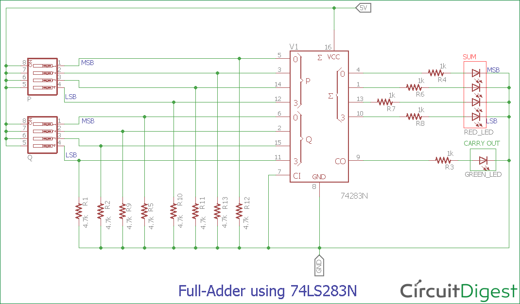
To demonstrate a practical Full Adder, we use the IC 74LS283N, a 4-bit full adder with carry look-ahead features. Here’s a list of components required:

  • 74LS283N IC

  • 4-pin DIP switches (2 pcs)

  • Red LEDs (4 pcs)

  • Green LED (1 pc)

  • 4.7k resistors (8 pcs)

  • 1k resistors (5 pcs)

  • Breadboard

  • Connecting wires

  • 5V adapter


Circuit Setup

Connect the VCC and Ground to pins 16 and 8, respectively.

Connect the first 4-bit number to pins 5, 3, 14, and 12 (P inputs).

Connect the second 4-bit number to pins 6, 2, 15, and 11.

The SUM outputs will be on pins 4, 1, 13, and 10.

Use 4.7k resistors on all input pins to set logic 0 when switches are off.

Use red LEDs for SUM outputs and a green LED for the Carry out bit.

For a visual demonstration, check out the video tutorial below where we show adding two 4-bit binary numbers using the 74LS283N IC.


Understanding Full Adder circuits is crucial for digital electronics. By combining half adders and using logic gates, we can build efficient circuits for adding binary numbers, with applications ranging from simple calculators to complex computer systems.


Watch the detailed video tutorial here: Full Adder Circuit Tutorial.


Monday, 3 June 2024

Calculating the Right Resistor for Your LED: A Step-by-Step Guide

Using an LED resistor calculator can help you determine the appropriate resistance for your LED circuit, ensuring your LEDs operate safely. Here's how to use one effectively.


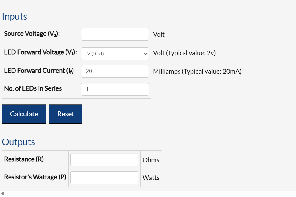
Inputs

  • Source Voltage (Vs): The total voltage from your power source, measured in volts.

  • LED Forward Voltage (Vf): The voltage drop across the LED, which varies by color (e.g., Red = 2V).

  • LED Forward Current (If): The current flowing through the LED, typically around 20mA.

  • Number of LEDs in Series: How many LEDs are connected in a series configuration.


Outputs

  • Resistance (R): The value of the resistor needed, measured in ohms.

  • Resistor's Wattage (P): The power rating of the resistor, measured in watts.


Why Use a Resistor with LEDs?

LEDs require a specific range of current to operate correctly. Exceeding this range can damage the LED. A resistor in series with the LED helps limit the current to a safe level.


How to Use the Calculator

Input Values: Enter the source voltage (Vs), LED forward voltage (Vf), LED forward current (If), and the number of LEDs in series.

Calculate: The calculator will provide the necessary resistor value (R) and its power rating (P).

LED Forward Voltage by Color

Red: 2V

Green: 2.1V

Blue/White: 3.6V

Yellow: 2.1V

Orange: 2.2V

Amber: 2.1V

Infrared: 1.7V


Calculation Equation

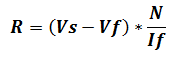
To find the resistor value mathematically, use the equation:


LED resistor calculation

​Where:

Vs: Source voltage

Vf: LED forward voltage

If: LED forward current (in amps)

N: Number of LEDs in series


Using an LED resistor calculator simplifies finding the right resistor to ensure your LEDs work safely and efficiently. By inputting your circuit parameters, you can quickly get the necessary resistance value and avoid potential damage to your LEDs.


To use the calculator, visit: LED Resistor Calculator.

Wednesday, 22 May 2024

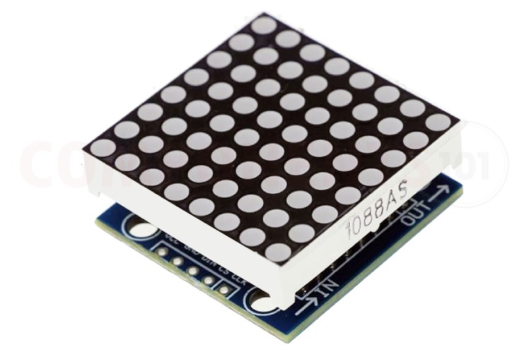
A Beginner's Guide to the MAX7219 8x8 LED Matrix Module

 The MAX7219 8x8 LED matrix module is a small but mighty display tool loved by hobbyists and tech enthusiasts alike. Let's break down what makes this module so cool and how you can use it in your own projects.


What is the MAX7219 LED Matrix Module?

The MAX7219 LED matrix module is a neat little gadget that makes it easy to control lots of LEDs at once. With it, you can light up to 64 individual LEDs in a grid pattern, showing characters, symbols, or even animations.


What Makes it Special?

  • Easy to Use: It's designed to be simple to connect and control, so you can focus on being creative.

  • Tiny but Powerful: Despite its small size, it can handle a lot of LEDs, giving you plenty of room to play.

  • Works with Many Devices: Whether you're using an Arduino, Raspberry Pi, or something else, chances are this module will play nicely with it.


How Do You Use It?

Connecting the MAX7219 module to your device is a piece of cake. Just hook up a few wires, and you're good to go. From there, you can start programming it to display whatever you want – the only limit is your imagination!


Tips for Troubleshooting

If things aren't going smoothly, don't panic! Here are a few things to check:


  • Power Supply: Make sure you're giving it enough juice – it likes to run on 5 volts.

  • Brightness: If the display looks dim or flickery, try adjusting the brightness settings.

  • Double-Check Connections: Sometimes, a loose wire is all that's standing between you and success.


What Can You Do with It?

The possibilities are endless! Use it to make your own DIY projects, create eye-catching signs, or even build interactive displays. Whether you're a seasoned pro or just getting started, the MAX7219 LED matrix module is sure to spark your creativity.


The MAX7219 LED matrix module may be small, but it's mighty. With its simple setup, compatibility with popular devices, and endless potential for creativity, it's the perfect tool for bringing your ideas to life. So what are you waiting for? Get out there and start making something amazing!


Full Video Tutorial : https://youtu.be/pHw3AokxRXM


Thursday, 16 May 2024

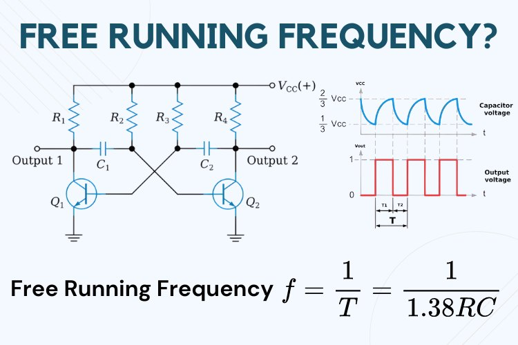
Calculate the Free-Running Frequency of Astable Multivibrators


Astable multivibrators, a fundamental component in electronics, operate continuously without external triggering, making them essential for generating periodic signals in various electronic devices. This article explores the calculation of the free-running frequency of astable multivibrators, shedding light on their functionality, applications, and significance.


What is an Astable Multivibrator?


An astable multivibrator is an oscillator circuit that alternates between its two unstable states without external triggering. Unlike monostable and bistable multivibrators, astable circuits lack a stable state, earning them the moniker of "free-running oscillators." They find applications in generating clock pulses, timing circuits, and light flashers, among others.


How Astable Multivibrator Works


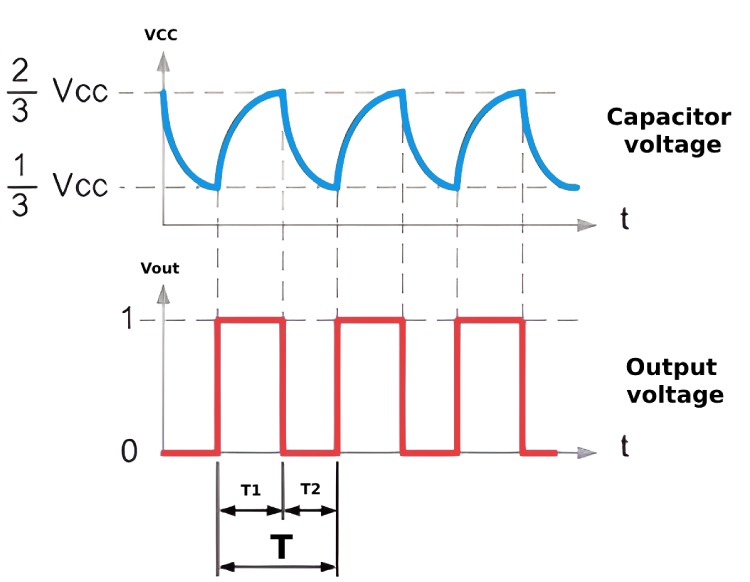
The operation of an astable multivibrator hinges on the charging and discharging cycles of capacitors within the circuit. Typically consisting of two amplifying elements in a feedback loop, such as transistors or operational amplifiers, the circuit's timing intervals are determined by the values of capacitors and resistors. This continuous switching between states produces a square wave output, essential for digital circuits.


Basic Astable Multivibrator Circuit


Constructed using transistors, resistors, and capacitors, a basic astable multivibrator circuit comprises two amplifiers arranged with regenerative feedback. The cycling between conducting and cut-off states of the amplifiers generates oscillations, with resistor-capacitor pairs determining timing intervals.


Calculating Free-Running Frequency


The free-running frequency, representing the oscillation rate of an astable multivibrator, is calculated using the formula: f = 1 / (1.38 * R * C), where R is resistance in ohms and C is capacitance in farads. For symmetrical output waveforms, where R2 = R3 and C1 = C2, the time period (T) simplifies to T = 1.38 * R * C. This frequency calculation enables designers to tailor multivibrator behavior to meet specific project requirements.


Applications and Importance


Astable multivibrators find widespread use in electronics, serving in pulse generation, timers, LED flashers, and alarm circuits. Their versatility and simplicity, coupled with the ability to adjust the free-running frequency by tweaking component values, make them indispensable in both amateur and professional electronic projects. The adaptability of astable multivibrators underscores their utility and relevance in modern electronics.


In conclusion, understanding the calculation of the free-running frequency of astable multivibrators provides valuable insights into their functionality and applications, empowering electronics enthusiasts and professionals alike to harness their potential in diverse projects.


Friday, 10 May 2024

L9110 Motor Driver IC: Design and Troubleshooting Tips

 The L9110 motor driver IC is a cost-effective solution for controlling DC motors in a variety of applications. With its wide input voltage range and bi-directional control capability, it offers versatility and simplicity for hobbyists and engineers alike.


Features of L9110


Low Quiescent Current: Operates efficiently with minimal power consumption.

Wide Supply Voltage Range: Compatible with voltages ranging from 2.5V to 12V.

High Current Output: Capable of delivering up to 800mA continuous current per channel.

TTL/CMOS Compatibility: Easily integrates with digital logic circuits for seamless control.

Built-in Clamp Diodes: Protects against reverse inductive load current for enhanced safety.


Applications of L9110: Robotics, printers, toys, DIY projects.

Alternatives to L9110: L293D, L298, TB6612FNG, DRV8833, MAX1508, TA6586,  DRV8871,MX1919.


Troubleshooting Tips


Circuit Resets: Ensure motor supply voltage is within the rated range and consider adding a capacitor parallel to the motor to mitigate voltage spikes.

Overheating IC: Address issues such as overloading, voltage spikes, or poor heat dissipation by adding capacitors to suppress spikes and ensuring proper ventilation.


Design Considerations


Proper Grounding: Establish a solid ground plane to minimize noise and interference.

Current Capacity: Ensure sufficient track width to handle high currents.

Decoupling Capacitors: Place capacitors close to power pins for efficient noise suppression.

Signal Tracks: Keep signal tracks short and direct for optimal performance.


The L9110 motor driver IC offers a simple and effective solution for controlling DC motors in various applications. With its compact size, versatile features, and ease of use, it's an excellent choice for hobbyists and professionals seeking reliable motor control. For detailed technical specifications and mechanical drawings, refer to the L9110 datasheet available here.