Showing posts with label arduino projects. Show all posts

Thursday, 7 May 2026

Automatic Waste Segregation System Using Arduino UNO Q

Automatic Waste Segregation System Using Arduino UNO Q

Waste segregation is important for recycling and environmental protection, but in daily life many people throw all waste into a single bin. To solve this problem, this project demonstrates an automatic waste segregation system using the Arduino UNO Q, Edge Impulse, and computer vision. The system can automatically identify different types of waste and sort them without manual effort.

This  Automatic Waste Segregation System project uses a USB camera and an AI-based object detection model to recognize waste materials such as:

  • Paper
  • Plastic
  • Cardboard
  • Battery

Once the object is detected, the system performs different actions using a servo motor and buzzer. Paper and cardboard are directed into the biodegradable section, plastic goes into the non-biodegradable section, and batteries trigger a buzzer alert because they are considered hazardous waste.

Why Arduino UNO Q?

The Arduino UNO Q is used as the main controller because it combines intelligent processing with reliable hardware control. Unlike traditional Arduino boards, it can handle both AI-based object detection and real-time hardware operations efficiently. This makes it ideal for smart automation projects like waste segregation.

Components Required

The project uses the following components:

  • Arduino UNO Q
  • USB Camera
  • Servo Motor
  • Buzzer
  • USB Hub
  • Jumper Wires
  • Cardboard Bin Structure
  • Laptop for programming
Components used in Smart Waste Segregation Project

Software Platforms Used

Edge Impulse

Edge Impulse is used to collect image data, label waste categories, and train the object detection model. The trained model is then optimized for embedded systems.

Arduino App Lab

Arduino App Lab is used to integrate the trained AI model with the hardware system. It manages communication between the Python application and the Arduino UNO Q.

How the System Works

Circuit  Diagram for Automatic Waste Segregation System

The USB camera continuously captures live video frames. The Edge Impulse object detection model analyzes each frame and identifies the waste type with a confidence score.

To avoid false detections, the system uses:

  • Confidence thresholds
  • Stability counters
  • Cooldown timers

When the same object is detected consistently, the system triggers the required action.

Waste Sorting Actions

Waste TypeAction
Paper/CardboardServo rotates to 0°
PlasticServo rotates to 180°
BatteryBuzzer activates

After sorting, the servo automatically returns to its default 90° position.

Python and Arduino Control

The project uses two interconnected programs:

Python Code

The Python application handles:

  • Camera input
  • Object detection
  • Stability checks
  • Sending commands to hardware

Arduino Code

The Arduino sketch controls:

  • Servo motor movement
  • Buzzer activation
  • Communication with the Python application

This combination enables smooth real-time waste detection and sorting.

Real-World Applications
Labelling Process of Different Items

This smart waste segregation system can be used in:

  • Homes
  • Schools and colleges
  • Offices
  • Shopping malls
  • Public waste collection systems
  • Smart city recycling solutions

It can also be used as an educational project for learning embedded AI, IoT, and automation.

Future Improvements

The system can be upgraded further by adding:

  • Detection for glass and metal waste
  • Mobile app monitoring
  • Solar-powered operation
  • Cloud-based waste analytics
  • LED indicators and voice feedback

These improvements can make the system more suitable for large-scale smart waste management applications.

This project presents a simple and practical automatic waste segregation system using Arduino UNO Q and Edge Impulse. By combining AI-based object detection with real-time hardware control, the system can automatically identify and sort waste materials efficiently.

The project demonstrates how embedded machine learning can be used to build low-cost smart recycling solutions that improve waste management and reduce environmental impact

https://circuitdigest.com 

Robotics Projects |Arduino Projects | Raspberry Pi Projects|

Monday, 20 April 2026

Arduino UNO Q Face Detection Project – A Simple Entry into Edge AI

Arduino UNO Q - Beginners Guide

From blinking LEDs to building full-fledged smart systems, Arduino boards have always been a go-to for makers. Now, things get a serious upgrade with the Arduino UNO Q, a board that blends the simplicity of Arduino with the power of modern computing.

In this you getting started with Arduino UNO Q   project, we explore something that once felt complex - real-time face detection - and make it surprisingly simple using the UNO Q and Arduino App Lab.

What Makes Arduino UNO Q Different?

Arduino UNO and UNO Q With Dimensions

Unlike traditional boards, the Arduino UNO Q isn’t just a microcontroller. It combines a powerful Linux-based processor with a real-time microcontroller. This means it can handle both high-level tasks like AI processing and low-level hardware control at the same time.

In simple terms, you get the best of both worlds:

  • Power for AI and vision tasks
  • Real-time control for sensors and hardware
  • Built-in WiFi and Bluetooth

That’s a big jump from the classic Arduino experience.

Project Idea: Face Detection Made Easy

Setup of UNO Q Web Camera and Laptop

This project uses a USB webcam to detect faces in real time. The UNO Q processes the video feed and highlights detected faces with bounding boxes.

The best part? You don’t need to write complex AI code. Arduino App Lab uses a brick-based system, where you simply connect functional blocks to build your program.

Hardware Setup

The setup is straightforward and beginner-friendly:

  • Arduino UNO Q
  • USB webcam
  • Laptop
  • Type-C hub (for connectivity)

You connect the UNO Q to your laptop using a USB-C hub, plug in the webcam, and you’re ready to go. This setup allows the board to interact with both the camera and the development environment smoothly.

Getting Started with Arduino App Lab

Instead of the traditional Arduino IDE, this project uses Arduino App Lab. It’s a visual programming environment where you drag and connect blocks (called “bricks”) to create applications.

Once the board is connected, you can:

  • Open example projects
  • Load the Face Detector example
  • Run the program instantly

No complicated setup, no deep AI coding required.

Running the Face Detection Program

After loading the example, just hit Run. Within a few seconds, a browser window opens showing the live camera feed.

The system detects faces and draws bounding boxes around them. You’ll also see a confidence score, which tells how accurate the detection is.

You can even tweak detection sensitivity using a slider, making it interactive and easy to experiment with.

Why This Project Stands Out

What makes this project interesting is how it simplifies something advanced. Face detection usually requires frameworks like TensorFlow or OpenCV setup. Here, it’s reduced to a few clicks.

It shows how the UNO Q bridges the gap between:

  • Beginner-friendly electronics
  • Advanced AI-based applications

Real-World Applications

This simple demo opens the door to many practical ideas:

  • Smart surveillance systems
  • Attendance tracking
  • Human-machine interaction
  • AI-based robotics

You can extend this further into face recognition, object detection, or even gesture-based control systems.

The Arduino UNO Q specifications change how we think about Arduino projects. It’s no longer limited to basic electronics - it steps into AI and edge computing without making things complicated.

This face detection project is a great starting point. It’s simple to build, easy to understand, and gives you a glimpse into what modern embedded systems can do.

If you’re someone moving from basic Arduino projects to something more advanced, this is exactly the kind of project that makes that transition smooth.

https://circuitdigest.com 

Robotics Projects |Arduino Projects | Raspberry Pi Projects|


Thursday, 26 February 2026

DIY Arduino Game Controller using Arduino Uno R4


Arduino Game Controller

Gaming is one of the best ways to relax and refresh the mind. Classic joystick-based games gave us simple and direct control using physical buttons and sticks. In this project, we recreate that experience by building a DIY Game Controller using Arduino Uno R4, combining retro-style control with modern electronics.

This Arduino Game Controller project is a great way to learn USB HID communication, input proce uses a joystick module and push buttons to control games on a computer. When connected through USB, the Arduino Uno R4 acts like a keyboard device, allowing games to detect inputs instantly without installing drivers.

Components Required

  • Arduino Uno R4
  • Joystick Module
  • 4 Push Buttons
  • Veroboard
  • Jumper Wires
Components Required


Working Principle

The joystick provides X and Y axis analog signals, which Arduino converts into arrow key movements.
Push buttons are mapped to keys like W, A, S, and D for game actions.

Using the Keyboard.h library, the Arduino sends real-time key press signals to the PC, making the setup function like a real game controller.

Circuit Diagram of game Controller


Hardware Connection

  • Joystick X → A0
  • Joystick Y → A1
  • Buttons → Digital Pins 2–5
  • Power → 5V & GND

Buttons use internal pull-up resistors, so no extra components are needed.

This Arduino Game Controller project is a great way to learn USB HID communication, input processing, and human–computer interaction. It transforms basic hardware into a functional gaming device while offering a fun hands-on electronics experience.

https://circuitdigest.com 

Robotics Projects |Arduino Projects | Raspberry Pi Projects|

Thursday, 22 May 2025

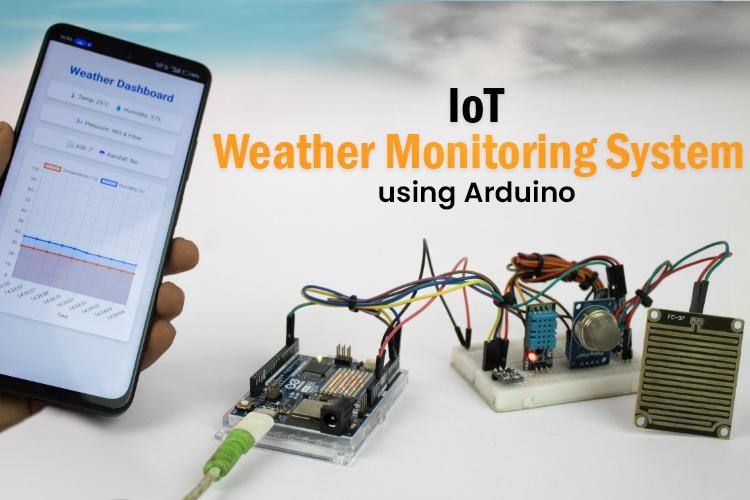
Weather Monitoring System Using Arduino UNO R4 WiFi

Weather Monitoring System

Learn how to create a simple IoT-based weather monitoring system using the Arduino UNO R4 WiFi. This project collects real-time data, such as temperature, humidity, air quality, rainfall, and atmospheric pressure, and displays the information on a local web dashboard. No cloud service or third-party platform is required, making this setup ideal for offline environments.

Features of the IoT Weather Monitoring System

  • Monitors temperature, humidity, air quality, pressure, and rainfall
  • Displays real-time readings on a local Wi-Fi dashboard
  • Operates without cloud connectivity
  • Built with Arduino UNO R4 WiFi, which includes onboard Wi-Fi
  • Easy to assemble and customize using basic electronic components

Components Required

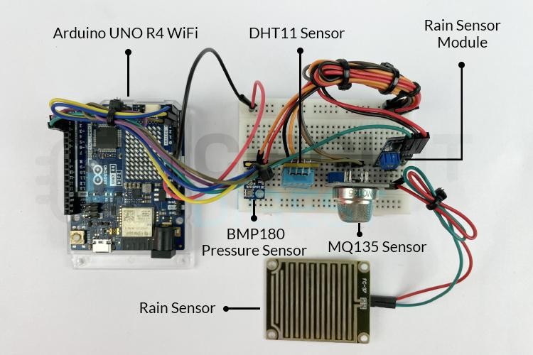
Components required to build an Arduino Weather Monitoring System


To build this system, you'll need the following:

  • Arduino UNO R4 WiFi
  • DHT11 – Temperature and Humidity Sensor
  • BMP180 – Pressure Sensor
  • MQ135 – Air Quality Sensor
  • Rain Sensor Module
  • Breadboard and Jumper Wires
  • USB Cable for Programming

Circuit Diagram and Assembly of IoT based Weather Station System

Circuit Diagram for Arduino-Based Weather Monitoring System

How It Works

Once powered on, each sensor reads environmental data. The Arduino UNO R4 WiFi processes this data and hosts a local web page that displays real-time values. Since the dashboard is served over your local network, there's no dependency on internet access or cloud platforms. Any device connected to the same Wi-Fi can access it.

Real-World Applications

This weather station can be adapted for various use cases:

  • Educational Projects – Great for learning about sensors, IoT, and data visualization
  • Smart Homes – Monitor indoor/outdoor conditions for automation
  • Gardening & Agriculture – Track weather changes for irrigation or crop planning
  • Offline Setups – Works in remote areas without relying on cloud platforms

For Arduino code and full tutorial: How to Build an IoT-Based Weather Monitoring System Using Arduino

https://circuitdigest.com 

Robotics Projects |Arduino Projects | Raspberry Pi Projects|

Wednesday, 21 May 2025

DIY Smart Helmet with Alcohol, Drowsiness and Theft Detection Using Arduino Uno

Road accidents are a major global concern, especially involving two-wheeler riders. Many of these accidents are due to drunk driving, drowsiness, or not wearing a helmet. The IoT Based Smart Helmet aims to reduce these risks by integrating safety features directly into the helmet. This project incorporates alcohol detection, drowsiness detection, helmet wear detection, and theft detection to ensure the rider’s safety and enforce responsible riding behavior.

Working Principle

The system is designed to prevent the bike from starting unless all safety conditions are satisfied:
  • IR sensor detects if the helmet is worn.
  • MQ-3 sensor checks for alcohol in breath.
  • If alcohol is detected, buzzer sounds and vehicle stays off.
  • Drowsiness detection monitors rider’s alertness.
  • RF transmitter sends data from helmet to vehicle.
  • Vehicle starts only if all safety conditions are met.
Parts Marking of Smart Helmet Transmitter Side

Transmitter Side

  • Arduino UNO R3 
  • 433 MHz RF Transmitter 
  • IR Sensor - wear detection and drowsiness detection
  • MQ-3 Sensor - alcohol detection
  • LED & Buzzer
  • Helmet 
  • Breadboard 
Receiver Side
  • Arduino UNO R3
  • 433 MHz RF Receiver
  • 16x2 LCD Display with I2C Module
  • 1-Channel Relay Module
  • LED & Buzzer
  • Breadboard
Sleep Detection By Smart Safety Helmet

Applications
  • Two-Wheeler Safety
  • Smart Transportation
  • Theft Prevention
  • Educational Tool
For full assembly details and code Smart Helmet using Arduino

Monday, 5 May 2025

Send SMS Using Arduino UNO R4 WiFi and CircuitDigest Cloud API

How to Send SMS with Arduino via Internet

This tutorial shows how to send an SMS using the Arduino UNO R4 Wi-Fi and the Circuit Digest Cloud API, without using a GSM module, by using board’s Wi-Fi capability to connect to the internet and send an HTTP request to the SMS API.

Components Required

  • Arduino UNO R4 Wi-Fi
  • USB cable
  • Arduino IDE
  • Wi-Fi connection
  • Circuit Digest Cloud account
  • A mobile number to receive SMS

Arduino Board Connection
The Arduino UNO R4 WiFi connects to the internet using built-in Wi-Fi and sends an HTTP POST request to the CircuitDigest Cloud API with the recipient’s phone number, your API key, and message. The cloud server processes the request and sends the SMS to the specified number via its SMS gateway.

Applications

  • Alerting
  • Automation
  • Monitoring
  • Agriculture
  • Education

This project demonstrates how to send SMS from an Arduino UNO R4 WiFi using CircuitDigest Cloud API. It's a useful method for sending notifications in simple IoT applications without needing additional hardware.

For in-depth explanation and code : How to Send SMS with Arduino UNO R4 via Internet?

Wednesday, 23 April 2025

DIY Smart Blind Stick Using Arduino Nano

Smart Blind Stick using Arduino and Ultrasonic sensor

Navigating daily environments can be difficult for visually impaired individuals. To improve mobility and safety, this project introduces a DIY smart blind stick using Arduino Nano, an ultrasonic sensor, and a buzzer. It’s simple, budget-friendly, and serves as a practical aid for obstacle detection. The system works by detecting nearby objects and alerting the user via sound and light signals.

How the Blind Stick Works

This Arduino-based stick functions as an assistive tool by constantly checking for nearby obstacles and triggering alerts. It includes:

  • Ultrasonic Sensor (HC-SR04): Detects objects by sending ultrasonic waves and receiving the reflected signal.
  • Arduino Nano: Acts as the central controller, calculating distance and triggering alerts.
  • Buzzer and LED: Provide audio and visual warnings depending on the proximity of obstacles.
Audio Based Obstacle Detection and Alerts Using Arduino


Obstacle Detection

The ultrasonic sensor emits a sound wave when triggered by the Arduino. When the wave hits an object, it reflects back and is received by the sensor’s echo pin. The time taken for the round trip helps calculate the distance.

Distance Calculation

The Arduino uses the following formula to calculate distance:

Distance = (Time taken by the signal to Hit and bounce back / 2) / 29.1

For example, a 500µs round-trip means the object is roughly 8.59 cm away.

Alerts

If the object is within 50 cm:

  • Buzzer: Emits a beep. The closer the object, the faster the beep.
  • LED: Flashes similarly, helping those with partial vision.

Components Required

  • Arduino Nano
  • HC-SR04 Ultrasonic Sensor
  • 5V Buzzer
  • LED
  • 220Ω Resistor
  • 9V Battery
  • On/Off Switch
  • Breadboard and Wires
  • PVC Pipe for stick body

Block Diagram

The block diagram includes the Arduino Nano at the center, connected to the ultrasonic sensor (for input) and buzzer/LED (for output). A 9V battery powers the system.

Block Diagram Representation of Arduino-Based Blind Stick

Circuit Diagram

The sensor’s VCC, TRIG, ECHO, and GND are connected to Arduino pins. The buzzer and LED are connected to output pins through resistors. The entire circuit is powered by the battery via a switch.

Note: The sensor draws around 15mA, which is safe to power directly from Arduino GPIO pins.

Hardware Assembly

All components are placed on a small breadboard and fixed to a PVC pipe using zip ties. The battery is mounted with double-sided tape. The sensor is positioned at the top to detect obstacles ahead.

Hardware Connections of Obstacle Detection Stick for the Blind

Arduino Code Overview

The code reads distance and triggers alerts based on it. It uses millis() for multitasking of the buzzer and LED.

Uploading Code

  1. Open Arduino IDE.
  2. Select the board: Arduino Nano (ATmega328P).
  3. Choose the correct COM port.
  4. Paste and upload the code.

Once uploaded, your Arduino Nano starts working as the control unit for the blind stick.

Final Assembly

Fix the entire circuit onto the PVC pipe. Position the ultrasonic sensor to face forward and secure components using zip ties or tape. Ensure the switch is easily accessible for quick power control.

Assembling Blind Stick Circuit on a PVC Pipe

This project is a basic yet functional solution to help people with vision challenges navigate safely. It uses minimal components, is easy to assemble, and can be enhanced further with features like GPS or vibration alerts. You can find the full code and diagrams on the GitHub repository in the original tutorial.

Thursday, 27 March 2025

Interfacing Arduino with Servo Motors and Potentiometer – Beginner’s Tutorial


Arduino Servo Motor


Whether you’re building a robotic arm, an automated door, or a pan-tilt camera system, servo motors are the go-to choice for accurate angular movement. With the help of this guide you can learn how to interface a servo motor with Arduino, make it work, and control its position with the help of provided code.

What is a Servo Motor?

A servo motor is a type of motor used in various applications to precisely control the position, speed, and angular rotation of mechanical systems. 

It consists of:

  • DC Motor – The main driver
  • Gear System – Reduces speed, increases torque
  • Control Circuit – Receives signals & adjusts position
  • Feedback Mechanism – Ensures accurate movement
SG90 Servo Motor Pinout


Unlike DC motors, servo motors rotate within a fixed range (0° to 180°) and hold their position when powered.

Components Required

For this project, you’ll need:

  • Arduino Uno
  • SG90 or MG995 Servo Motor
  • Jumper Wires
  • External Power Source (if using a high-torque servo)
pinout of the potentiometer


Circuit Diagram of Interfacing Arduino with Servo Motors and Potentiometer

Circuit Diagram of Interfacing Arduino with Servo Motors and Potentiometer

Applications of Servo Motors

  • Robotic Arms & Grippers
  • Automated Doors & Windows
  • RC Cars & Airplanes
  • Pan-Tilt Camera Systems
  • DIY Animatronics & Smart Toys

Servo motors are easy to use and extremely useful for precise motion control in Arduino projects. With just a few lines of code, you can make them rotate, hold positions, and automate movements in your projects.

Friday, 8 March 2024

How to Interface Ultrasonic Sensors with Arduino?


In this tutorial, we'll explore the process of connecting an
ultrasonic sensor to an Arduino board and displaying distance measurements on an LCD. Our goal is to provide a detailed understanding of the setup, operation, and coding involved in this project.

Components Required:


  • Arduino board (e.g., Arduino Uno)

  • HC-SR04 Ultrasonic Sensor

  • I2C LCD Display (e.g., 16x2 characters)

  • Jumper wires


Understanding the HC-SR04 Ultrasonic Sensor:


The HC-SR04 ultrasonic sensor has four pins:


  • VCC: Supply pin

  • GND: Ground pin

  • Trig: Trigger pin

  • Echo: Echo pin


Previous Projects:


We've employed the HC-SR04 with Arduino, Raspberry Pi, and PIC microcontroller in various projects, including:


Distance measurement with Arduino

Interfacing HC-SR04 with PIC microcontroller

Raspberry Pi obstacle-avoiding robot

IoT dumpster monitoring with Arduino & ESP8266


Working Principle:


The ultrasonic sensor emits high-frequency sound waves and detects their reflections. It comprises a transducer, which emits and receives ultrasonic waves, and signal processing circuitry to measure the time taken for the waves to travel and return.


Circuit Connection:


Connect the ultrasonic sensor's trig and echo pins to Arduino pins 4 and 5, respectively. This configuration enables the Arduino to trigger the sensor and measure the time taken for the echo pulse to return.


Arduino Code for Ultrasonic Sensor:


The Arduino code initializes serial communication and sets up the trigger and echo pins. It triggers the sensor, measures the duration of the echo pulse, and calculates the distance based on the speed of sound. The distance measurement is displayed on the Serial Monitor.


Adding an LCD Display:


Enhance the project by connecting an I2C LCD display to the Arduino. Use the SDA and SCL pins (A4 and A5 for Arduino Uno) for communication, along with VCC and GND. The LCD will provide real-time distance measurements alongside the serial output.


Practical Applications:


Explore various projects utilizing ultrasonic sensors, such as:


Interfacing with Raspberry Pi Pico for distance measurement

Building a smart blind stick for visually impaired individuals

Implementing an IoT-based smart dustbin management system using NodeMCU


This comprehensive guide offers detailed insights into interfacing an ultrasonic sensor with an Arduino and displaying distance measurements on an LCD. By following the steps outlined here, you can gain a better understanding of ultrasonic sensor operation and embark on exciting projects leveraging this technology.


For a complete tutorial, visit: https://youtu.be/bOZ5QdASm30