Showing posts with label PIC microcontroller. Show all posts

Friday, 8 March 2024

How to Interface Ultrasonic Sensors with Arduino?


In this tutorial, we'll explore the process of connecting an
ultrasonic sensor to an Arduino board and displaying distance measurements on an LCD. Our goal is to provide a detailed understanding of the setup, operation, and coding involved in this project.

Components Required:


  • Arduino board (e.g., Arduino Uno)

  • HC-SR04 Ultrasonic Sensor

  • I2C LCD Display (e.g., 16x2 characters)

  • Jumper wires


Understanding the HC-SR04 Ultrasonic Sensor:


The HC-SR04 ultrasonic sensor has four pins:


  • VCC: Supply pin

  • GND: Ground pin

  • Trig: Trigger pin

  • Echo: Echo pin


Previous Projects:


We've employed the HC-SR04 with Arduino, Raspberry Pi, and PIC microcontroller in various projects, including:


Distance measurement with Arduino

Interfacing HC-SR04 with PIC microcontroller

Raspberry Pi obstacle-avoiding robot

IoT dumpster monitoring with Arduino & ESP8266


Working Principle:


The ultrasonic sensor emits high-frequency sound waves and detects their reflections. It comprises a transducer, which emits and receives ultrasonic waves, and signal processing circuitry to measure the time taken for the waves to travel and return.


Circuit Connection:


Connect the ultrasonic sensor's trig and echo pins to Arduino pins 4 and 5, respectively. This configuration enables the Arduino to trigger the sensor and measure the time taken for the echo pulse to return.


Arduino Code for Ultrasonic Sensor:


The Arduino code initializes serial communication and sets up the trigger and echo pins. It triggers the sensor, measures the duration of the echo pulse, and calculates the distance based on the speed of sound. The distance measurement is displayed on the Serial Monitor.


Adding an LCD Display:


Enhance the project by connecting an I2C LCD display to the Arduino. Use the SDA and SCL pins (A4 and A5 for Arduino Uno) for communication, along with VCC and GND. The LCD will provide real-time distance measurements alongside the serial output.


Practical Applications:


Explore various projects utilizing ultrasonic sensors, such as:


Interfacing with Raspberry Pi Pico for distance measurement

Building a smart blind stick for visually impaired individuals

Implementing an IoT-based smart dustbin management system using NodeMCU


This comprehensive guide offers detailed insights into interfacing an ultrasonic sensor with an Arduino and displaying distance measurements on an LCD. By following the steps outlined here, you can gain a better understanding of ultrasonic sensor operation and embark on exciting projects leveraging this technology.


For a complete tutorial, visit: https://youtu.be/bOZ5QdASm30


Friday, 1 June 2018

PIC Microcontroller Communication Tutorials

In the vast system of embedded applications, no microcontroller can perform all the activities by itself and so it has to communicate to other devices to share information. There are many different types of communication protocols used by microcontrollers to share these information’s, but the most used ones are USART, IIC, SPI and CAN. Each communication protocol has its own advantage and disadvantage. To learn how to work with these communication protocols in PIC microcontroller, Below are few tutorials which provide the complete guide to use these communication protocols.

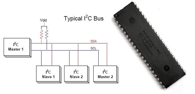
1. PIC Microcontroller I2C Communication
I2C Communication with PIC Microcontroller PIC16F877

The term IIC stands for “Inter Integrated Circuits”. It is normally denoted as I2C or I squared C or even as 2-wire interface protocol (TWI) at some places but it all means the same. I2C is a synchronous communication protocol meaning, both the devices that are sharing the information must share a common clock signal. It has only two wires to share information out of which one is used for the cock signal and the other is used for sending and receiving data.
Click the link to learn more about PIC microcontroller I2C communication

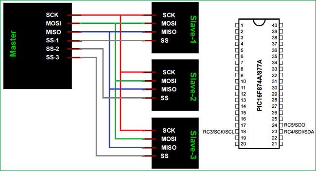
2. PIC Microcontroller SPI communication
PIC16F877A PIC Microcontroller SPI Communication Tutorial

The term SPI stands for “Serial Peripheral Interface”. It is a common communication protocol that is used to send data between two microcontrollers or to read/write data from a sensor to a microcontroller. It is also used to communicate with SD cards, shift registers, Display controllers and much more. Know more about PIC SPI communication

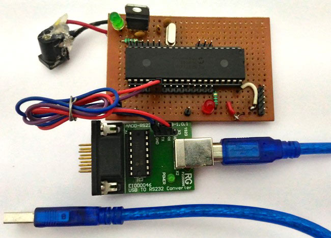
3. PIC Microcontroller UART Communication
UART Communication using PIC Microcontroller

Here we have used PIC16F877A MCU, it has a module called “Addressable Universal Synchronous Asynchronous Receiver and Transmitter” shortly known as USART. USART is a two wire communication system in which the data flow serially. USART is also a full-duplex communication, means you can send and receive data at the same time which can be used to communicate with peripheral devices, such as CRT terminals and personal computers. Know more about PIC UART communication.

4. CAN Communication with PIC Microcontroller
Bring communication and connectivity in your embedded design to the next level with Microchip's Controller Area Network (CAN) bus solutions technology. Originally created for automotive applications, the CAN bus protocol is a high-speed, reliable communication protocol for applications requiring robust communications at bit rates reaching 8 Mbps. Incorporating the CAN bus protocol into your design is a low-cost, reliable way to function in a difficult electrical environment with a high degree of real-time capability. Learn more about CAN communication here.

Sunday, 15 January 2017

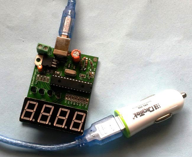
Car Battery Voltage Monitoring using PIC Microcontroller


In this project we are going to make a PIC based Car Battery Monitoring system on PCB. Here, we have designed a PCB using EASYEDA online PCB simulator and designer. This Car Battery Monitoring Circuit is used to monitor the power of Car Battery by just plugging it into the power outlet on the dashboard of a car. The PCB also has the option to use it as Voltage Measurement tool or Voltmeter without using USB car charger. We have attached a terminal block here to measure the voltage of other power sources, just by connecting two wires in it from the power source. 

Friday, 6 January 2017

PIC Microcontroller Tutorial: Learn about Timers

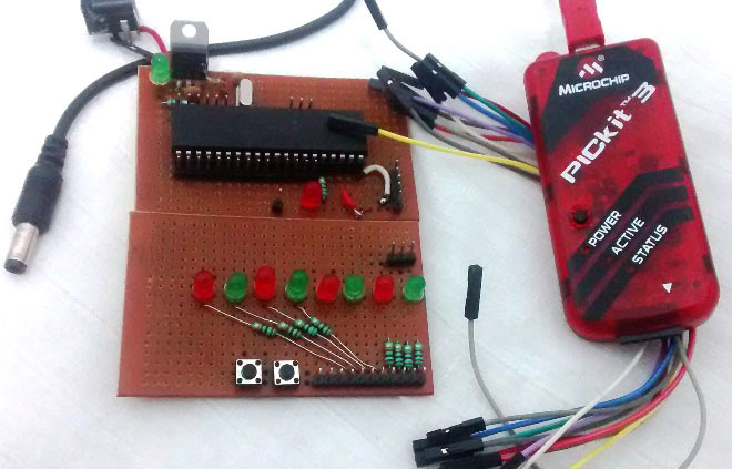
In this PIC microcontroller tutorial series, this tutorial will help you to learn and use Timers in PIC16F877A. In our previous tutorials, we had started with Introduction to PIC and MPLABX IDE, then we wrote our first PIC program to blink the LED using PIC and then made a LED Blinking Sequence by using delay function in PIC Microcontroller. Now let us use the same LED Blinking sequence which we have used in previous tutorial hardware and with this we will Learn How to use Timers in our PIC MCU. We have just added one more button in LED board for this tutorial. Go through the tutorial to learn more.

To learn more about the basic concepts of PIC microcontrollers, and get some interesting DIY projects, keep visiting www.circuitdigest.com