Showing posts with label DIYProjects. Show all posts

Friday, 13 March 2026

DC Motor Speed Control Using GSM with Arduino – SMS-Based Motor Control

DC Motor Control Using GSM

Automation and remote control systems are becoming increasingly important in modern engineering. In many situations, operating machines manually is not always practical, especially in large industrial setups, agricultural fields, or remote locations. Remote control technologies help solve this problem by allowing devices to be operated from a distance without direct human interaction.

In this project, we build a DC motor speed control using GSM and Arduino. Instead of controlling the motor with physical switches, the motor can be operated remotely using SMS commands sent from a mobile phone. The Arduino receives these commands through a GSM module and controls the motor accordingly.

Components Required

This project uses several commonly available electronic components:

  • Arduino Uno
  • SIM800L GSM Module
  • L298N Motor Driver
  • DC Motor
  • Logic Level Shifter
  • Breadboard
  • Jumper Wires
  • External Power Supply
  • Arduino IDE
Components Required for the DC Motor Control Using GSM

The Arduino Uno acts as the main controller that processes incoming SMS commands and sends control signals to the motor driver. The SIM800L GSM module receives SMS messages from the user’s phone and forwards them to the Arduino. The L298N motor driver is responsible for controlling the speed and direction of the DC motor.

Because the GSM module and Arduino operate at different voltage levels, a logic level shifter is used to ensure safe communication between the two devices.

Circuit Overview

Circuit Diagram of DC Motor Control Using GSM

The circuit connects the Arduino, GSM module, motor driver, and motor together to create a complete control system.

The GSM module communicates with the Arduino through serial communication. When an SMS message is received, the module sends the message data to the Arduino. Since the SIM800L operates at a lower voltage level than the Arduino, a level translator is used to convert the signals safely.

The Arduino processes the received command and sends control signals to the L298N motor driver. The driver then supplies the required current to the motor and determines its direction and speed.

Motor direction is controlled through two input pins on the motor driver, while motor speed is controlled using Pulse Width Modulation (PWM) from the Arduino. A separate power supply is usually required for the motor and GSM module to ensure stable operation.

All components share a common ground connection, which is essential for proper communication between devices.

How GSM-Based Motor Control Works

The working principle of this system is simple and efficient.

When the circuit is powered on, the Arduino and GSM module are initialized. The GSM module connects to the mobile network and waits for incoming SMS messages. Meanwhile, the Arduino continuously monitors the serial interface for new data from the GSM module.

The user sends an SMS command from a mobile phone to control the motor. Each message contains a predefined command that represents a specific motor action.

For example:

  • FWD200Rotate the motor forward at speed level 200

  • REV150Rotate the motor in reverse at speed level 150

  • STOPStop the motor immediately

When the GSM module receives the SMS, it forwards the message content to the Arduino through serial communication. The Arduino reads the message and checks whether it matches one of the predefined commands.

If the command indicates forward rotation, the Arduino sets the input pins of the motor driver accordingly so the motor rotates in the forward direction. If the command indicates reverse rotation, the logic signals are reversed to change the direction.

For speed control, the Arduino generates a PWM signal on the enable pin of the motor driver. By changing the PWM duty cycle, the motor speed can be increased or decreased smoothly.

Using this method, the motor can be controlled remotely from anywhere within GSM network coverage.

Real-World Applications

GSM-based motor control systems have several practical applications.

  • Automated gates
  • Security barriers
  • Home automation systems 

Because GSM communication does not require internet connectivity, the system works reliably even in areas with limited internet access.

The DC motor speed control using GSM and Arduino project demonstrates a practical method for remotely controlling motors using SMS commands. By combining an Arduino Uno, SIM800 GSM module, and L298N motor driver, the motor’s speed and direction can be controlled without physical interaction.

This project also introduces important concepts such as GSM communication, PWM-based speed control, serial interfacing, and motor driver operation. With small modifications, the system can be expanded to control multiple motors or integrated into larger automation systems.

Overall, this project provides a simple and effective solution for remote motor control in real-world applications. 

https://circuitdigest.com 

Robotics Projects |Arduino Projects | Raspberry Pi Projects|

Friday, 21 March 2025

How to use L298N Motor Driver with Arduino?

How to use L298N Motor Driver with Arduino


What is the L298N Motor Driver Module?

The L298N Motor Driver Module is a high power motor driver module for driving DC and Stepper Motors.. It supports motors operating at 5V to 35V and offers features like:

  • Forward & Reverse Motor Control
  • PWM Speed Control
  • Overheating & Overcurrent Protection
  • Separate Power Input for Motors & Logic Control
Circuit Diagram for Interfacing L298N Motor Driver with Arduino


Components Required
Here’s what you’ll need for this project:
  • Arduino Uno
  • L298N Motor Driver Module
  • DC Motor (5V–12V)
  • Power Source (Battery or Adapter)
  • Jumper Wires
Components needed for interfacing the L298N Driver Module with Arduino.

This project explains how to interface the L298N Motor Driver Module with Arduino to control DC motors efficiently. The L298N allows you to regulate motor speed and direction using PWM signals, making it perfect for robotics, automation, and motorized projects. With this tutorial, you'll learn to drive motors forward, backward, and at variable speeds, enabling you to build remote-controlled cars, conveyor systems, and robotic arms.


Tuesday, 11 March 2025

How to Build a Bidirectional Visitor Counter using Arduino

How-to-Build-a-Bidirectional-Counter-Using-Arduino-and-IR-Sensors
What is a Bidirectional Counter?

A bidirectional counter counts objects or people moving in two directions, incrementing the count for one direction and decrementing for the opposite. It is commonly used in:

  • Automatic door entry systems
  • Visitor counters in malls, offices, and stations
  • Industrial conveyor belt monitoring

Components Required

To build this project, you'll need:

  • Arduino Uno
  • IR Sensors (2x)
  • 7-Segment Display or LCD
  • Resistors & Capacitors
  • Jumper Wires & Breadboard
Hardware-Connection-of-Bidirectional-Counter-System-using-IR-Sensors (1)


This project demonstrates how to use the L298N Motor Driver Module with Arduino to control the speed and direction of a DC motor. By leveraging PWM (Pulse Width Modulation) signals, you can achieve precise motion control, making it ideal for robotics, automation, and motorized systems. Whether you're a beginner or an advanced maker, this tutorial will help you understand motor control concepts and apply them to your own projects.

Monday, 3 June 2024

Calculating the Right Resistor for Your LED: A Step-by-Step Guide

Using an LED resistor calculator can help you determine the appropriate resistance for your LED circuit, ensuring your LEDs operate safely. Here's how to use one effectively.


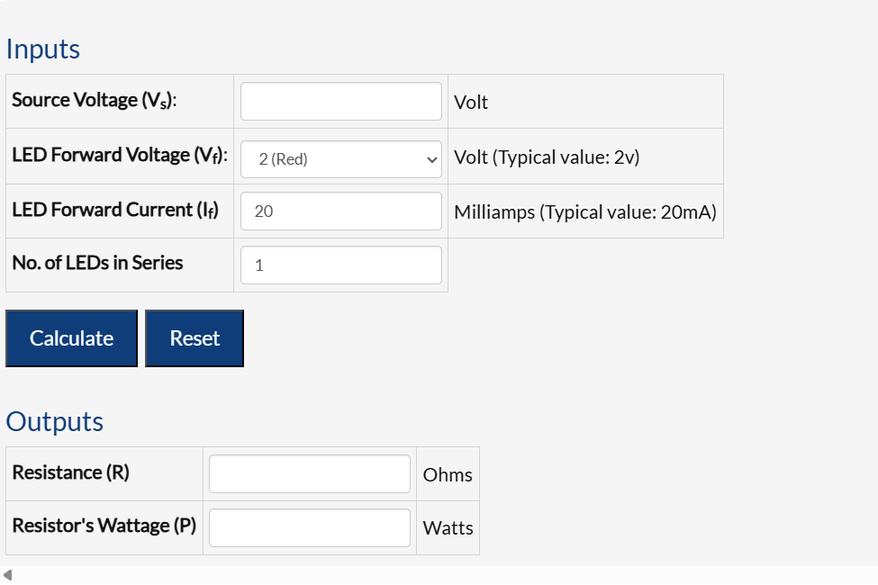
Inputs

  • Source Voltage (Vs): The total voltage from your power source, measured in volts.

  • LED Forward Voltage (Vf): The voltage drop across the LED, which varies by color (e.g., Red = 2V).

  • LED Forward Current (If): The current flowing through the LED, typically around 20mA.

  • Number of LEDs in Series: How many LEDs are connected in a series configuration.


Outputs

  • Resistance (R): The value of the resistor needed, measured in ohms.

  • Resistor's Wattage (P): The power rating of the resistor, measured in watts.


Why Use a Resistor with LEDs?

LEDs require a specific range of current to operate correctly. Exceeding this range can damage the LED. A resistor in series with the LED helps limit the current to a safe level.


How to Use the Calculator

Input Values: Enter the source voltage (Vs), LED forward voltage (Vf), LED forward current (If), and the number of LEDs in series.

Calculate: The calculator will provide the necessary resistor value (R) and its power rating (P).

LED Forward Voltage by Color

Red: 2V

Green: 2.1V

Blue/White: 3.6V

Yellow: 2.1V

Orange: 2.2V

Amber: 2.1V

Infrared: 1.7V


Calculation Equation

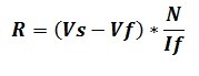
To find the resistor value mathematically, use the equation:


LED resistor calculation

​Where:

Vs: Source voltage

Vf: LED forward voltage

If: LED forward current (in amps)

N: Number of LEDs in series


Using an LED resistor calculator simplifies finding the right resistor to ensure your LEDs work safely and efficiently. By inputting your circuit parameters, you can quickly get the necessary resistance value and avoid potential damage to your LEDs.


To use the calculator, visit: LED Resistor Calculator.

Thursday, 16 May 2024

Calculate the Free-Running Frequency of Astable Multivibrators


Astable multivibrators, a fundamental component in electronics, operate continuously without external triggering, making them essential for generating periodic signals in various electronic devices. This article explores the calculation of the free-running frequency of astable multivibrators, shedding light on their functionality, applications, and significance.


What is an Astable Multivibrator?


An astable multivibrator is an oscillator circuit that alternates between its two unstable states without external triggering. Unlike monostable and bistable multivibrators, astable circuits lack a stable state, earning them the moniker of "free-running oscillators." They find applications in generating clock pulses, timing circuits, and light flashers, among others.


How Astable Multivibrator Works


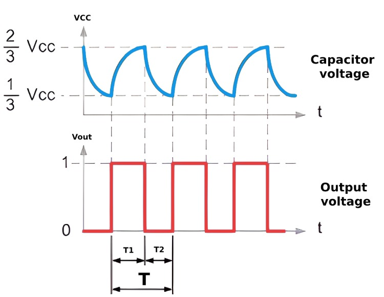
The operation of an astable multivibrator hinges on the charging and discharging cycles of capacitors within the circuit. Typically consisting of two amplifying elements in a feedback loop, such as transistors or operational amplifiers, the circuit's timing intervals are determined by the values of capacitors and resistors. This continuous switching between states produces a square wave output, essential for digital circuits.


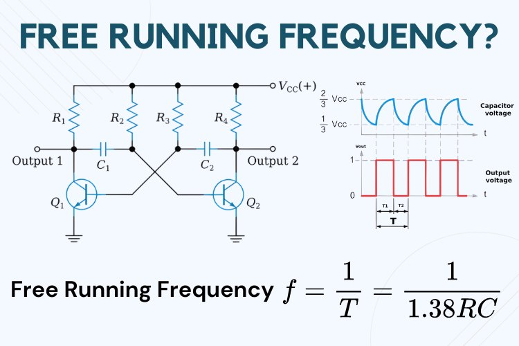
Basic Astable Multivibrator Circuit


Constructed using transistors, resistors, and capacitors, a basic astable multivibrator circuit comprises two amplifiers arranged with regenerative feedback. The cycling between conducting and cut-off states of the amplifiers generates oscillations, with resistor-capacitor pairs determining timing intervals.


Calculating Free-Running Frequency


The free-running frequency, representing the oscillation rate of an astable multivibrator, is calculated using the formula: f = 1 / (1.38 * R * C), where R is resistance in ohms and C is capacitance in farads. For symmetrical output waveforms, where R2 = R3 and C1 = C2, the time period (T) simplifies to T = 1.38 * R * C. This frequency calculation enables designers to tailor multivibrator behavior to meet specific project requirements.


Applications and Importance


Astable multivibrators find widespread use in electronics, serving in pulse generation, timers, LED flashers, and alarm circuits. Their versatility and simplicity, coupled with the ability to adjust the free-running frequency by tweaking component values, make them indispensable in both amateur and professional electronic projects. The adaptability of astable multivibrators underscores their utility and relevance in modern electronics.


In conclusion, understanding the calculation of the free-running frequency of astable multivibrators provides valuable insights into their functionality and applications, empowering electronics enthusiasts and professionals alike to harness their potential in diverse projects.


Sunday, 14 April 2024

Choosing the Right Battery Charging IC: A Simple Guide for Your Projects


Selecting the appropriate battery charging IC is essential for maximizing the performance and durability of battery-powered devices. Whether you're working on DIY electronics or developing commercial products, understanding how to pick the right
battery charging IC can make a significant difference. Let's dive into a detailed guide to help you navigate this crucial aspect of electronics design.

Why Battery Charging ICs Matter


Battery charging ICs are responsible for managing the charging process of rechargeable batteries, ensuring they are charged safely and efficiently. By selecting the right IC, you can optimize the charging speed, protect against potential risks like overcharging or overheating, and extend the lifespan of your batteries.


Key Factors to Consider


  • Battery Type Compatibility: Start by identifying the type of battery you intend to charge, such as lithium-ion, lithium polymer, or NiMH. Different battery chemistries have specific charging requirements, and your IC should support these needs.

  • Charging Voltage and Current: Determine the ideal charging voltage and current specifications for your battery. The charging IC must provide the necessary levels to suit your battery's charging profile without causing damage.

  • Charging Speed: Evaluate the charging speed supported by the IC. While faster charging is desirable, it should be balanced with considerations for battery safety and longevity.

  • Input Power Source: Consider the power source available for charging, such as USB ports or AC adapters. Ensure that the charging IC is compatible with the input voltage and current ratings of your power source.

  • Safety Features: Look for built-in safety features like overcharge protection, over-discharge protection, thermal regulation, and short-circuit protection. These features are crucial for safeguarding both the battery and the charging circuit.

  • Size and Package Type: Check the physical dimensions and package type of the IC, especially if space is limited in your device. Common package types include QFN, DFN, and BGA.

  • Additional Features: Explore extra features offered by the IC, such as charging status indicators, battery temperature monitoring, and programmable charging profiles. These features can enhance charging performance and user experience.


How to Choose


  1. Research and Specifications: Start by researching the specifications and requirements of your battery and device. Understand the charging parameters needed for optimal performance.

  2. Comparison: Compare different battery charging ICs based on the identified criteria. Refer to datasheets and application notes from manufacturers for detailed information.

  3. Evaluation and Testing: If possible, prototype and test the selected ICs under real-world conditions to assess factors like charging efficiency and reliability.

  4. Feedback and Reviews: Seek insights from industry experts, forums, and user reviews to gather practical feedback on specific IC models.


By following this structured approach and considering important factors like battery type, charging specifications, safety features, and additional functionalities, you can confidently select the right battery charging IC for your electronic projects. This thoughtful decision-making process will ensure optimal battery performance and device reliability, ultimately enhancing the overall user experience.


Choosing the right battery charging IC requires careful consideration of various factors, but it's a critical step in the design process. By prioritizing safety, efficiency, and compatibility, you can create battery-powered devices that deliver outstanding performance and durability. Whether you're a hobbyist or a professional, mastering the art of selecting the right IC will elevate your electronics projects to the next level.