Showing posts with label basic circuits. Show all posts

Tuesday, 24 March 2026

Simple Optocoupler Tester Circuit for Quick and Reliable Testing

Optocouplers are small but critical components used in many electronic circuits for isolation and signal transfer. The tricky part? When they fail, they usually don’t show any visible signs. Everything looks fine on the outside, but internally, either the LED or the phototransistor might stop working.

That’s where a simple optocoupler tester circuit becomes extremely useful. Instead of guessing or relying only on a multimeter, this small tester gives you clear results in seconds.

What This Tester Does

This optocoupler tester is designed to quickly check whether an optocoupler is working properly or not. It verifies two key things:

  • Whether the internal LED (input side) is functioning
  • Whether the output side responds to the light

The circuit is simple, battery-powered, and doesn’t require any measuring tools. It’s perfect for lab use, repair work, or even checking salvaged components.

How the Circuit Works


The working principle is based on optical isolation.

When you press the push button:

  • Current flows through the internal LED of the optocoupler
  • A red LED glows, indicating the input side is active
  • The emitted light triggers the output transistor
  • A green LED turns ON if the output side is working

So, in just one press, you get a complete functional check.

The results are easy to understand:

  • Both LEDs ON → Optocoupler is good
  • Only red LED ON → Output side is faulty
  • No LEDs ON → Input LED or connection issue
  • Green LED only → Possible wiring error or short

This makes troubleshooting fast and beginner-friendly.

Components Used

The best part of this project is how simple it is.

You only need:

  • Optocoupler (for testing)
  • Red LED (input indication)
  • Green LED (output indication)
  • Push button
  • 3.7V Li-ion battery
  • Two 470Ω resistors
  • IC sockets (4-pin & 6-pin)
  • Dot board

Using IC bases is a smart choice here. It lets you test multiple optocouplers without soldering or risking heat damage.

Why Not Just Use a Multimeter?

You can test an optocoupler using a multimeter, but it has limitations.

A multimeter:

  • Can check only the input LED properly
  • Cannot fully verify the output response
  • Requires manual probing and interpretation

This tester, on the other hand:

  • Checks both input and output together
  • Gives instant visual results
  • Takes less than 2 seconds per test

So for regular use, a dedicated tester is much more practical.

Where This Is Useful

This simple circuit is surprisingly helpful in many situations:

  • Electronics labs
  • Repair and maintenance work
  • Testing bulk components
  • Educational projects
  • Verifying reused or salvaged parts

It saves time and prevents faulty components from being used in circuits.

This Optocoupler Tester Circuit is a perfect example of a small project that solves a real problem. It’s simple, low-cost, and extremely practical.

Instead of spending time guessing or troubleshooting blindly, you get a clear pass/fail result instantly. And once you build it, you’ll find yourself using it again and again.

If you’re working with optocouplers regularly, this is definitely a must-have tool on your workbench.

https://circuitdigest.com 

Robotics Projects |Arduino Projects | Raspberry Pi Projects|

Tuesday, 10 March 2026

DIY LED Chaser Circuit with 555 Timer IC

Built an LED Chaser Circuit with 555 Timer IC and CD4017

LEDs are one of the most fun components to experiment with in electronics. With just a few LEDs and basic components, you can create eye-catching lighting effects like running lights, festival decorations, and dynamic blinking patterns.

One of the most popular beginner circuits is the LED Chaser Circuit using a 555 Timer IC and CD4017 Counter IC. This circuit makes LEDs turn on one after another in sequence, creating a smooth running light effect.

If you've ever seen decorative lighting on signboards, festival displays, or DIY projects, there’s a good chance a similar LED chaser circuit is working behind the scenes.

In this guide, we’ll walk through how to build a simple LED chaser circuit using the 555 timer and CD4017, explain how it works, and show how you can modify it for different lighting effects.

What is an LED Chaser Circuit?

An LED chaser circuit is an electronic circuit where LEDs turn on and off in sequence, creating a moving or chasing light pattern.

Instead of all LEDs lighting up at once, the circuit activates them one at a time in order, producing a running effect.

This project uses two main ICs:

  • 555 Timer IC – Generates timing pulses
  • CD4017 Decade Counter IC – Controls the LED sequence

The combination of these two chips makes it easy to build a simple and reliable LED running light circuit.

Components Required

The LED chaser circuit is a great beginner project because it uses only a few components.

  1. NE555 Timer IC
  2. CD4017 Decade Counter IC
  3. 1K resistor
  4. 50K potentiometer (variable resistor)
  5. 10µF capacitor
  6. 0.1µF ceramic capacitor
  7. 10 LEDs
  8. 220Ω resistors (one for each LED)
  9. Breadboard
  10. Jumper wires
  11. 9V battery or DC power supply

Understanding the 555 Timer IC

555 TImer IC Pinout

The 555 Timer IC is one of the most widely used chips in electronics. It can generate timing signals, pulses, and oscillations.

In this project, the 555 timer operates in astable mode, which means it continuously generates square wave pulses.

These pulses act as the clock signal for the CD4017 counter.

Important Pins of 555 Timer

Pin 1 Ground
Pin 2 Trigger
Pin 3 Output (clock pulses)
Pin 4 Reset
Pin 5 Control voltage
Pin 6 Threshold
Pin 7 Discharge
Pin 8 VCC (power supply)

The output pulses from Pin 3 drive the CD4017 counter.

CD4017 Decade Counter Explained


CD4017 IC Pinout


The CD4017 IC is a decade counter with 10 outputs (Q0–Q9).

Every time it receives a clock pulse, it activates the next output pin.

So the sequence looks like this:

Q0 → Q1 → Q2 → Q3 → ... → Q9 → Q0

Each LED is connected to one output pin, which creates the chasing light pattern.

Important CD4017 Pins

Q0–Q9 LED outputs
Pin 8 Ground
Pin 14 Clock input
Pin 15 Reset
Pin 16 Power supply

The clock signal from the 555 timer goes to Pin 14 of the CD4017.

LED Chaser Circuit Diagram

LED Chaser Circuit Diagram

In the circuit:

  • The 555 timer generates pulses
  • The CD4017 counts these pulses
  • Each output turns on one LED at a time

A potentiometer is used to control the speed of the LED sequence.

This means you can adjust how fast or slow the LEDs chase each other.

Step-by-Step Circuit Assembly

Follow these steps to build the LED chaser circuit.

Step 1

Connect the 9V battery to the breadboard power rails.

Step 2

Insert the 555 Timer IC onto the breadboard.

Step 3

Add the timing components:

  • 1K resistor
  • 50K potentiometer
  • 10µF capacitor

These components determine the pulse frequency.

Step 4

Place the CD4017 IC on the breadboard.

Step 5

Connect Pin 3 of the 555 timer to Pin 14 of CD4017.

Step 6

Connect 10 LEDs to outputs Q0–Q9 using 220Ω resistors.

Step 7

Add a 0.1µF capacitor between VCC and GND for stability.

Step 8

Double-check wiring before applying power.

When powered, the LEDs should begin chasing in sequence.

How the LED Chaser Circuit Works

Working Setup of all Components

The working principle is simple:

  1. The 555 timer generates clock pulses continuously.
  2. These pulses are sent to the CD4017 counter.
  3. Each pulse moves the active output to the next pin.
  4. The LEDs connected to these outputs light up sequentially.
  5. After the last LED, the sequence repeats.

The result is a smooth running LED pattern.

Adjusting LED Speed

The 50K potentiometer controls the speed of the LED chasing pattern.

High Resistance        - Slower LED movement
Medium Resistance   - Moderate speed
Low Resistance         - Faster chasing effect

This lets you customize the visual effect.

Troubleshooting Common Issues


No LEDs glow        -Power supply issue                 -Check battery polarity
LEDs glow dimly        - Missing resistors                    -Add 220Ω resistors
LEDs not sequential       -Clock signal missing          -Verify connection between 555 and CD4017
Pattern stops early         -Reset pin wiring wrong          -Connect Pin 15 to GND
Speed not changing -Potentiometer wiring wrong   -Recheck connections

Enhancements and Modifications

Once you build the basic circuit, you can experiment with several upgrades.

1. More LEDs

You can cascade multiple CD4017 ICs to control 20 or more LEDs.

2. Bidirectional LED Chaser

Using additional counters, you can create back-and-forth LED patterns.

3. RGB LED Effects

Replace single LEDs with RGB LEDs for colorful lighting patterns.

4. Music-Reactive LED Chaser

Replace the 555 timer with a microphone circuit to synchronize lights with music.

Applications of LED Chaser Circuits

LED chaser circuits are used in many applications, including:

  • Decorative lighting displays
  • Festival lighting patterns
  • LED signboards
  • DIY electronics projects
  • Learning digital electronics
  • Advertising displays

Because the circuit is simple and inexpensive, it’s a great project for students and hobbyists.

Conclusion

The LED Chaser Circuit using 555 Timer and CD4017 is a classic beginner electronics project. It demonstrates how analog timing circuits and digital counters can work together to produce interesting lighting effects.

With just a few components, you can create dynamic running lights that are perfect for learning electronics, experimenting with LED displays, or building decorative lighting projects.

Once you understand the basics, you can expand the circuit with more LEDs, different patterns, and even sound-controlled lighting effects.

So grab a breadboard, connect the components, and watch your LEDs come alive with a chasing light effect.

https://circuitdigest.com 

Robotics Projects |Arduino Projects | Raspberry Pi Projects|

Thursday, 8 January 2026

Low-Voltage LED Booster Using a Simple Joule Thief Circuit


Joule Thief Circuit

A Joule Thief is a simple and clever voltage booster circuit that allows you to extract usable energy from nearly dead batteries. Even when a battery’s voltage drops too low to power an LED directly, a Joule Thief can step it up and keep the LED glowing. This makes it a great beginner project for learning basic power electronics and inductive switching.

What Is a Joule Thief?

A Joule Thief circuit is a self-oscillating boost circuit that uses a transistor, a resistor, and a coupled inductor (toroid coil) to generate high-voltage pulses from a low-voltage source. These pulses are enough to drive LEDs or other small loads using batteries that would otherwise be discarded.

Components Required

  • NPN transistor (e.g., 2N2222 or 2N3904)
  • 1 kΩ resistor
  • Toroidal core with two windings
  • LED
  • 1.5 V battery
  • Breadboard and jumper wires
Components Required Joule Thief Circuit


How the Circuit Works

When power is applied, the transistor rapidly switches ON and OFF due to positive feedback through the coil. As the magnetic field in the inductor collapses, it generates a high-voltage spike. This boosted voltage lights the LED even though the battery voltage is very low. The cycle repeats continuously, producing visible light.

Why It’s Useful

  • Extracts energy from almost-dead batteries
  • Demonstrates boost converter basics
  • Uses very few, low-cost components
  • Excellent learning project for beginners
Joule-Theif-Circuit-Diagram


The Simple Joule Thief circuit is a perfect example of how smart circuit design can make the most out of limited power. It’s easy to build, educational, and surprisingly effective - ideal for anyone starting out in electronics or exploring voltage booster concepts.


Monday, 31 July 2017

3 Basic Electronics Circuits to Learn Electronics

Here are 3 simple electronic circuits by using basic electronic components.

1. Simple Preamp Circuit


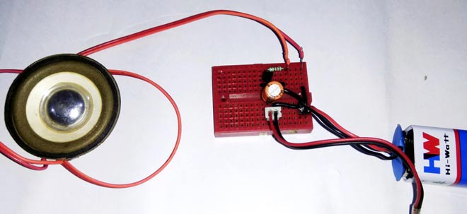
"Sometimes we use a Preamp Circuit in circuits for pre-amplification of weak signal when the audio source sound level is too low. Pre-amlification of low level signals is necessary before feeding them into a power source, for clear and noiseless sound." So here we will build this Simple Preamplifier Circuit using NPN transistor BC547.

2. Bike Turning Signal


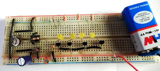
This fancy Car/Bike Turning Indicator Circuit uses a 555 Timer IC along with four yellow color LEDs glowing one by one in a particular pattern and we can control the speed or frequency of this LED indicator by simply turning a Potentiometer. This works in the similar pattern in which bike or car's turning signal works. Here you can find all the required details to build this circuit.

3. PWM Generator Circuit


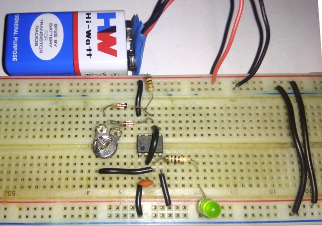
PWM is very important concept in electronics engineering. To understand this concept and make a simple circuit with this, we used a 555 timer IC along with a potentiometer, a capacitor and few registers which generates PWM signal. You can learn about PWM concept with building this basic circuit.