Showing posts with label Circuit. Show all posts

Monday, 13 April 2026

Getting Started with SU-03T Offline Voice Recognition Module for Embedded Systems

Low-Cost Offline Voice Recognition Module Alternatives to VC-02

Voice control is becoming a natural way to interact with electronics, but most systems still rely heavily on the internet. That’s where this project stands out. Instead of sending voice data to the cloud, it processes everything locally using the SU-03T Offline Voice Recognition Module, making the system faster, more reliable, and completely independent of internet connectivity.

Why Go Offline?

Cloud-based voice systems are powerful, but they come with limitations. They need a stable internet connection, can introduce delays, and often raise privacy concerns since voice data is processed remotely. Offline voice recognition solves all of these issues by keeping everything on the device itself.

In this SU-03T Offline Voice Recognition Module project, the module listens, processes, and responds instantly - no internet required.

How the System Works

Circuit Diagram of Offline Voice Module

The setup is straightforward. A microphone captures the user’s voice, and the module processes it internally. Each spoken command is compared with a predefined set of commands stored in the module’s memory. When a match is found, the system triggers an action.

For demonstration, we use simple commands like turning LEDs ON and OFF. When you say a command, the module recognises it and immediately controls the corresponding GPIO pin.

At the same time, a speaker provides audio feedback, making the interaction more natural and responsive.

Components Used

Hardware Connection of Offline Voice Module

The hardware is simple and beginner-friendly:

  • SU-03T Voice Recognition Module
  • Microphone (for input)
  • Speaker (for audio feedback)
  • LEDs with resistors (for output indication)
  • USB-to-TTL converter (for programming)
  • Breadboard and jumper wires

This minimal setup makes it easy to build and test quickly.

Setting Up Voice Commands

Before using the system, voice commands need to be configured using the Ai-Thinker SDK platform. You can define:

  • Wake word (like “Hello”)
  • Command phrases (like “Turn on light”)
  • System responses (like “Turning on the light”)

Once configured, the firmware is generated and flashed into the module. After that, the system is ready to recognise commands in real time.

Key Features

What makes this project interesting is its simplicity combined with functionality:

  • Fully offline voice recognition
  • Instant response with low latency
  • No dependency on Wi-Fi or cloud APIs
  • Customisable commands and responses
  • Direct control of GPIO devices

It’s a great example of edge processing in embedded systems.

Applications

This system can be extended far beyond just LEDs.

In smart homes, it can control lights, fans, and appliances without needing internet access. For assistive technology, it allows hands-free control for elderly or physically challenged users.

In industrial environments, it can be used where internet connectivity is unreliable. It also fits well in automotive systems for basic voice controls.

For students and hobbyists, it’s a perfect entry point into voice-based embedded systems.

Limitations to Keep in Mind

Since the module relies on predefined commands, accuracy depends on how clearly the commands are trained and spoken. Background noise and pronunciation can affect recognition.

Also, compared to advanced cloud AI systems, the command set is limited - but for most practical use cases, it’s more than enough.

This offline voice control project shows how powerful local processing can be. By using the SU-03T module, you can build a responsive, private, and reliable voice-controlled system without any internet dependency.

If you’re exploring embedded systems or automation, this is a great project to understand how voice interfaces can be implemented efficiently at the device level. 

https://circuitdigest.com 

Robotics Projects |Arduino Projects | Raspberry Pi Projects|

Tuesday, 24 March 2026

Simple Optocoupler Tester Circuit for Quick and Reliable Testing

Optocouplers are small but critical components used in many electronic circuits for isolation and signal transfer. The tricky part? When they fail, they usually don’t show any visible signs. Everything looks fine on the outside, but internally, either the LED or the phototransistor might stop working.

That’s where a simple optocoupler tester circuit becomes extremely useful. Instead of guessing or relying only on a multimeter, this small tester gives you clear results in seconds.

What This Tester Does

This optocoupler tester is designed to quickly check whether an optocoupler is working properly or not. It verifies two key things:

  • Whether the internal LED (input side) is functioning
  • Whether the output side responds to the light

The circuit is simple, battery-powered, and doesn’t require any measuring tools. It’s perfect for lab use, repair work, or even checking salvaged components.

How the Circuit Works


The working principle is based on optical isolation.

When you press the push button:

  • Current flows through the internal LED of the optocoupler
  • A red LED glows, indicating the input side is active
  • The emitted light triggers the output transistor
  • A green LED turns ON if the output side is working

So, in just one press, you get a complete functional check.

The results are easy to understand:

  • Both LEDs ON → Optocoupler is good
  • Only red LED ON → Output side is faulty
  • No LEDs ON → Input LED or connection issue
  • Green LED only → Possible wiring error or short

This makes troubleshooting fast and beginner-friendly.

Components Used

The best part of this project is how simple it is.

You only need:

  • Optocoupler (for testing)
  • Red LED (input indication)
  • Green LED (output indication)
  • Push button
  • 3.7V Li-ion battery
  • Two 470Ω resistors
  • IC sockets (4-pin & 6-pin)
  • Dot board

Using IC bases is a smart choice here. It lets you test multiple optocouplers without soldering or risking heat damage.

Why Not Just Use a Multimeter?

You can test an optocoupler using a multimeter, but it has limitations.

A multimeter:

  • Can check only the input LED properly
  • Cannot fully verify the output response
  • Requires manual probing and interpretation

This tester, on the other hand:

  • Checks both input and output together
  • Gives instant visual results
  • Takes less than 2 seconds per test

So for regular use, a dedicated tester is much more practical.

Where This Is Useful

This simple circuit is surprisingly helpful in many situations:

  • Electronics labs
  • Repair and maintenance work
  • Testing bulk components
  • Educational projects
  • Verifying reused or salvaged parts

It saves time and prevents faulty components from being used in circuits.

This Optocoupler Tester Circuit is a perfect example of a small project that solves a real problem. It’s simple, low-cost, and extremely practical.

Instead of spending time guessing or troubleshooting blindly, you get a clear pass/fail result instantly. And once you build it, you’ll find yourself using it again and again.

If you’re working with optocouplers regularly, this is definitely a must-have tool on your workbench.

https://circuitdigest.com 

Robotics Projects |Arduino Projects | Raspberry Pi Projects|

Wednesday, 11 March 2026

Arduino Automatic Toll Gate System Project with RFID Payment and Servo Control

Automatic Toll Gate System Project using Arduino

Toll collection is a common process on highways where vehicles stop to pay a fee before continuing their journey. Traditional toll booths often require manual payment, which can lead to traffic delays and long queues. Automation helps solve this problem by making the process faster and more efficient.

In this project, we build an Automatic Toll Gate System using Arduino that detects vehicles, reads RFID cards, verifies payment, and opens the gate automatically. This project is a great introduction to real-world automation using sensors, RFID technology, and microcontrollers.

It is especially suitable for students, beginners, and Arduino enthusiasts who want to understand how simple electronics can automate everyday systems.

What is an Automatic Toll Gate System?

Circuit Diagram Automatic Toll Gate System using Arduino

An automatic toll gate system allows vehicles to pass through a toll booth without manual payment handling. Instead of cash transactions, the system uses RFID cards that store user information and balance.

When a vehicle approaches the toll gate, an IR sensor detects its presence. The driver then places an RFID card near the reader. The system scans the card and checks if it is valid and has enough balance to pay the toll.

If the card is valid and the balance is sufficient, the toll amount is deducted automatically. The gate then opens using a servo motor, allowing the vehicle to pass. After the vehicle crosses the gate, another sensor detects its exit and the gate closes again.

This process makes toll collection quick, automatic, and contactless.

Components Required

Components Automated Toll Gate RFID

The project uses simple and easily available components, including:

  • Arduino Uno
  • RFID RC522 Reader Module
  • RFID Cards or Tags
  • Two IR Sensor Modules
  • SG90 Servo Motor
  • Red LED and Green LED
  • Breadboard and Jumper Wires
  • 5V Power Supply or USB Power

The Arduino acts as the central controller, while the RFID module verifies the card. IR sensors detect vehicles, and the servo motor controls the gate.

Working of the Automatic Toll Gate System

Block Diagram

The system works in a sequence of simple steps.

First, the toll gate remains closed while the system waits for a vehicle to arrive. When a vehicle approaches, the entry IR sensor detects it and signals the Arduino to begin the authentication process.

Next, the driver scans the RFID card. The RFID reader reads the card’s unique ID and sends it to the Arduino. The program compares this ID with stored card IDs and checks the available balance.

If the card is valid and has enough balance, the toll amount is deducted. The green LED turns on, and the servo motor rotates to open the gate.

The vehicle then passes through the gate. When the vehicle crosses the exit IR sensor, the Arduino receives a signal indicating that the vehicle has left the toll area. The servo motor then moves back to close the gate, and the system resets for the next vehicle.

If the card is invalid or the balance is insufficient, the red LED lights up and the gate remains closed.

Arduino Code Overview

The Arduino code controls the entire toll system. It starts by including libraries required for SPI communication, RFID reading, and servo motor control.

In the setup section, the Arduino initializes all connected hardware components, including the RFID reader, sensors, LEDs, and the servo motor.

The loop function continuously checks whether a vehicle is detected by the entry IR sensor. When a vehicle is detected, the system waits for an RFID card scan.

If the scanned card matches a stored card and has sufficient balance, the Arduino opens the gate. Otherwise, access is denied.

Real-World Applications

Although this is a learning project, the concept is widely used in real life. Automatic toll collection systems are used on highways to reduce congestion and speed up vehicle movement.

Similar RFID-based systems are also used in parking lots, office buildings, gated communities, and industrial facilities to control vehicle access.

Conclusion

The Automatic Toll Gate System using Arduino is a simple and practical project that demonstrates how automation works in real-world applications.

By combining RFID technology, sensors, and motor control, the system can detect vehicles, verify payments, and operate a toll gate automatically. This project helps beginners learn important concepts such as Arduino programming, sensor integration, and RFID communication.

With further improvements like IoT connectivity or LCD displays, this project can easily be expanded into a more advanced smart toll management system.

https://circuitdigest.com 

Robotics Projects |Arduino Projects | Raspberry Pi Projects|

Tuesday, 10 March 2026

DIY LED Chaser Circuit with 555 Timer IC

Built an LED Chaser Circuit with 555 Timer IC and CD4017

LEDs are one of the most fun components to experiment with in electronics. With just a few LEDs and basic components, you can create eye-catching lighting effects like running lights, festival decorations, and dynamic blinking patterns.

One of the most popular beginner circuits is the LED Chaser Circuit using a 555 Timer IC and CD4017 Counter IC. This circuit makes LEDs turn on one after another in sequence, creating a smooth running light effect.

If you've ever seen decorative lighting on signboards, festival displays, or DIY projects, there’s a good chance a similar LED chaser circuit is working behind the scenes.

In this guide, we’ll walk through how to build a simple LED chaser circuit using the 555 timer and CD4017, explain how it works, and show how you can modify it for different lighting effects.

What is an LED Chaser Circuit?

An LED chaser circuit is an electronic circuit where LEDs turn on and off in sequence, creating a moving or chasing light pattern.

Instead of all LEDs lighting up at once, the circuit activates them one at a time in order, producing a running effect.

This project uses two main ICs:

  • 555 Timer IC – Generates timing pulses
  • CD4017 Decade Counter IC – Controls the LED sequence

The combination of these two chips makes it easy to build a simple and reliable LED running light circuit.

Components Required

The LED chaser circuit is a great beginner project because it uses only a few components.

  1. NE555 Timer IC
  2. CD4017 Decade Counter IC
  3. 1K resistor
  4. 50K potentiometer (variable resistor)
  5. 10µF capacitor
  6. 0.1µF ceramic capacitor
  7. 10 LEDs
  8. 220Ω resistors (one for each LED)
  9. Breadboard
  10. Jumper wires
  11. 9V battery or DC power supply

Understanding the 555 Timer IC

555 TImer IC Pinout

The 555 Timer IC is one of the most widely used chips in electronics. It can generate timing signals, pulses, and oscillations.

In this project, the 555 timer operates in astable mode, which means it continuously generates square wave pulses.

These pulses act as the clock signal for the CD4017 counter.

Important Pins of 555 Timer

Pin 1 Ground
Pin 2 Trigger
Pin 3 Output (clock pulses)
Pin 4 Reset
Pin 5 Control voltage
Pin 6 Threshold
Pin 7 Discharge
Pin 8 VCC (power supply)

The output pulses from Pin 3 drive the CD4017 counter.

CD4017 Decade Counter Explained


CD4017 IC Pinout


The CD4017 IC is a decade counter with 10 outputs (Q0–Q9).

Every time it receives a clock pulse, it activates the next output pin.

So the sequence looks like this:

Q0 → Q1 → Q2 → Q3 → ... → Q9 → Q0

Each LED is connected to one output pin, which creates the chasing light pattern.

Important CD4017 Pins

Q0–Q9 LED outputs
Pin 8 Ground
Pin 14 Clock input
Pin 15 Reset
Pin 16 Power supply

The clock signal from the 555 timer goes to Pin 14 of the CD4017.

LED Chaser Circuit Diagram

LED Chaser Circuit Diagram

In the circuit:

  • The 555 timer generates pulses
  • The CD4017 counts these pulses
  • Each output turns on one LED at a time

A potentiometer is used to control the speed of the LED sequence.

This means you can adjust how fast or slow the LEDs chase each other.

Step-by-Step Circuit Assembly

Follow these steps to build the LED chaser circuit.

Step 1

Connect the 9V battery to the breadboard power rails.

Step 2

Insert the 555 Timer IC onto the breadboard.

Step 3

Add the timing components:

  • 1K resistor
  • 50K potentiometer
  • 10µF capacitor

These components determine the pulse frequency.

Step 4

Place the CD4017 IC on the breadboard.

Step 5

Connect Pin 3 of the 555 timer to Pin 14 of CD4017.

Step 6

Connect 10 LEDs to outputs Q0–Q9 using 220Ω resistors.

Step 7

Add a 0.1µF capacitor between VCC and GND for stability.

Step 8

Double-check wiring before applying power.

When powered, the LEDs should begin chasing in sequence.

How the LED Chaser Circuit Works

Working Setup of all Components

The working principle is simple:

  1. The 555 timer generates clock pulses continuously.
  2. These pulses are sent to the CD4017 counter.
  3. Each pulse moves the active output to the next pin.
  4. The LEDs connected to these outputs light up sequentially.
  5. After the last LED, the sequence repeats.

The result is a smooth running LED pattern.

Adjusting LED Speed

The 50K potentiometer controls the speed of the LED chasing pattern.

High Resistance        - Slower LED movement
Medium Resistance   - Moderate speed
Low Resistance         - Faster chasing effect

This lets you customize the visual effect.

Troubleshooting Common Issues


No LEDs glow        -Power supply issue                 -Check battery polarity
LEDs glow dimly        - Missing resistors                    -Add 220Ω resistors
LEDs not sequential       -Clock signal missing          -Verify connection between 555 and CD4017
Pattern stops early         -Reset pin wiring wrong          -Connect Pin 15 to GND
Speed not changing -Potentiometer wiring wrong   -Recheck connections

Enhancements and Modifications

Once you build the basic circuit, you can experiment with several upgrades.

1. More LEDs

You can cascade multiple CD4017 ICs to control 20 or more LEDs.

2. Bidirectional LED Chaser

Using additional counters, you can create back-and-forth LED patterns.

3. RGB LED Effects

Replace single LEDs with RGB LEDs for colorful lighting patterns.

4. Music-Reactive LED Chaser

Replace the 555 timer with a microphone circuit to synchronize lights with music.

Applications of LED Chaser Circuits

LED chaser circuits are used in many applications, including:

  • Decorative lighting displays
  • Festival lighting patterns
  • LED signboards
  • DIY electronics projects
  • Learning digital electronics
  • Advertising displays

Because the circuit is simple and inexpensive, it’s a great project for students and hobbyists.

Conclusion

The LED Chaser Circuit using 555 Timer and CD4017 is a classic beginner electronics project. It demonstrates how analog timing circuits and digital counters can work together to produce interesting lighting effects.

With just a few components, you can create dynamic running lights that are perfect for learning electronics, experimenting with LED displays, or building decorative lighting projects.

Once you understand the basics, you can expand the circuit with more LEDs, different patterns, and even sound-controlled lighting effects.

So grab a breadboard, connect the components, and watch your LEDs come alive with a chasing light effect.

https://circuitdigest.com 

Robotics Projects |Arduino Projects | Raspberry Pi Projects|

Thursday, 8 January 2026

Low-Voltage LED Booster Using a Simple Joule Thief Circuit


Joule Thief Circuit

A Joule Thief is a simple and clever voltage booster circuit that allows you to extract usable energy from nearly dead batteries. Even when a battery’s voltage drops too low to power an LED directly, a Joule Thief can step it up and keep the LED glowing. This makes it a great beginner project for learning basic power electronics and inductive switching.

What Is a Joule Thief?

A Joule Thief circuit is a self-oscillating boost circuit that uses a transistor, a resistor, and a coupled inductor (toroid coil) to generate high-voltage pulses from a low-voltage source. These pulses are enough to drive LEDs or other small loads using batteries that would otherwise be discarded.

Components Required

  • NPN transistor (e.g., 2N2222 or 2N3904)
  • 1 kΩ resistor
  • Toroidal core with two windings
  • LED
  • 1.5 V battery
  • Breadboard and jumper wires
Components Required Joule Thief Circuit


How the Circuit Works

When power is applied, the transistor rapidly switches ON and OFF due to positive feedback through the coil. As the magnetic field in the inductor collapses, it generates a high-voltage spike. This boosted voltage lights the LED even though the battery voltage is very low. The cycle repeats continuously, producing visible light.

Why It’s Useful

  • Extracts energy from almost-dead batteries
  • Demonstrates boost converter basics
  • Uses very few, low-cost components
  • Excellent learning project for beginners
Joule-Theif-Circuit-Diagram


The Simple Joule Thief circuit is a perfect example of how smart circuit design can make the most out of limited power. It’s easy to build, educational, and surprisingly effective - ideal for anyone starting out in electronics or exploring voltage booster concepts.


Thursday, 22 May 2025

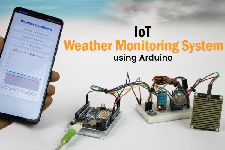
Weather Monitoring System Using Arduino UNO R4 WiFi

Weather Monitoring System

Learn how to create a simple IoT-based weather monitoring system using the Arduino UNO R4 WiFi. This project collects real-time data, such as temperature, humidity, air quality, rainfall, and atmospheric pressure, and displays the information on a local web dashboard. No cloud service or third-party platform is required, making this setup ideal for offline environments.

Features of the IoT Weather Monitoring System

  • Monitors temperature, humidity, air quality, pressure, and rainfall
  • Displays real-time readings on a local Wi-Fi dashboard
  • Operates without cloud connectivity
  • Built with Arduino UNO R4 WiFi, which includes onboard Wi-Fi
  • Easy to assemble and customize using basic electronic components

Components Required

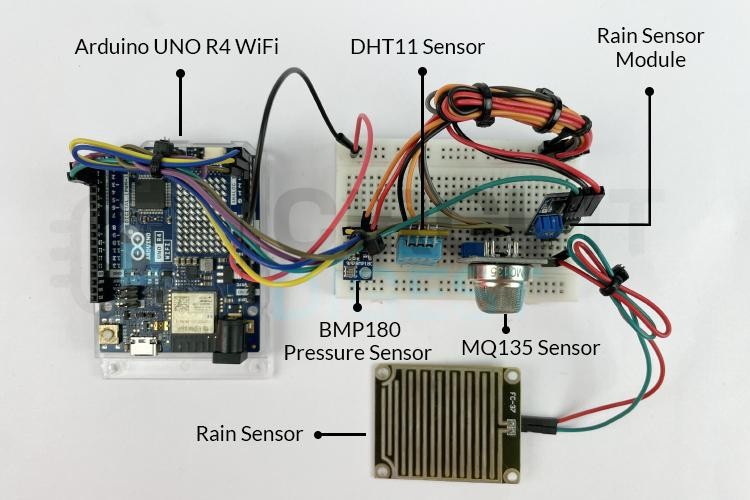
Components required to build an Arduino Weather Monitoring System


To build this system, you'll need the following:

  • Arduino UNO R4 WiFi
  • DHT11 – Temperature and Humidity Sensor
  • BMP180 – Pressure Sensor
  • MQ135 – Air Quality Sensor
  • Rain Sensor Module
  • Breadboard and Jumper Wires
  • USB Cable for Programming

Circuit Diagram and Assembly of IoT based Weather Station System

Circuit Diagram for Arduino-Based Weather Monitoring System

How It Works

Once powered on, each sensor reads environmental data. The Arduino UNO R4 WiFi processes this data and hosts a local web page that displays real-time values. Since the dashboard is served over your local network, there's no dependency on internet access or cloud platforms. Any device connected to the same Wi-Fi can access it.

Real-World Applications

This weather station can be adapted for various use cases:

  • Educational Projects – Great for learning about sensors, IoT, and data visualization
  • Smart Homes – Monitor indoor/outdoor conditions for automation
  • Gardening & Agriculture – Track weather changes for irrigation or crop planning
  • Offline Setups – Works in remote areas without relying on cloud platforms

For Arduino code and full tutorial: How to Build an IoT-Based Weather Monitoring System Using Arduino

https://circuitdigest.com 

Robotics Projects |Arduino Projects | Raspberry Pi Projects|

Thursday, 24 April 2025

Types of Current Transformers: A Comprehensive Guide

Types of Transformers

Current transformers (CTs) are important in modern electrical systems, allowing safe measurement and protection in high-current setups like power plants and substations. They convert high AC currents into lower, manageable values for monitoring.

What is a Current Transformer?

A current transformer is a step-down transformer that converts high current in its primary winding to a smaller, proportional current in its secondary winding. This makes it possible to safely monitor high-voltage circuits using instruments like ammeters, relays, and energy meters.

  • Primary Winding: Connected in series with the high-current line.
  • Secondary Winding: Connected to meters or protective relays.
  • Isolation: Both windings are electrically isolated and wrapped around a magnetic core.
Current Transformer Working and Symbol

Types of Current Transformers Based on Applications

  • Metering Current Transformers

These are used for accurate measurement of electrical consumption. Commonly found in residential and industrial metering systems, they are small in size and made from high-grade laminated silica steel. They ensure safe and precise current measurements for billing and monitoring purposes.

  • Protection Current Transformers

Designed to protect electrical systems during fault conditions, these CTs are connected to protective relays that trip the circuit during overcurrent or short-circuit scenarios. They have larger cores made of cold-rolled silicon steel to handle high fault currents (up to 10–20 times the rated value) without saturation.

Current Transformers Based on Applications

Types of Current Transformers Based on Construction

Current transformers can also be classified based on their construction, which affects how they are installed and used in different electrical setups. The main types include bar-type, cable-type, bushing-type, and block-type CTs, each suited for specific environments and current ranges.

Types of Current Transformers Based on Phases

  • Single-Phase CTs

These transformers handle single-phase power systems and are widely used in residential and commercial power distribution. They are straightforward in design and easy to maintain.

  • Three-Phase CTs

These contain three cores (or a three-phase core) and offer simultaneous current measurement across all three phases. They're commonly used in industries, power plants, and energy management systems.

Current Transformer Types Based on Phases

Types of Current Transformers Based on Core Types

Current transformers can also be categorized based on the type of magnetic core used, which directly influences their performance, accuracy, and suitability for different applications. The main core types include wound core, toroidal (ring) core, and split core CTs.

Current transformers come in various forms to serve different roles in electrical systems, from measuring to protection, from compact indoor setups to large-scale industrial environments. Choosing the right type of CT depends on the application, system voltage, and space constraints.

For more in-depth details: Types of Current Transformers

Wednesday, 7 February 2024

What are the different types of Fuse and Where to use them?


A fuse is a special device used in electrical circuits to protect them from damage caused by too much electric current. It works by containing a material that can melt when the current passing through it becomes too high. This melting breaks the circuit, stopping the flow of electricity and preventing further damage. There are different types of fuses for different types of circuits, like those used in homes, cars, and even in high-voltage power lines.

Fuses are divided into two main categories: AC and DC fuses. AC fuses are used in circuits where electricity flows back and forth in a specific pattern, like what we use in our homes. DC fuses, on the other hand, are used in circuits where electricity flows in only one direction, like in batteries or solar panels. Understanding how fuses work and the different types available helps to keep electrical systems safe and working properly.  Learn more information about fuses through the provided article -  different types of Fuse 


Saturday, 21 November 2015

Emergency Light Circuit

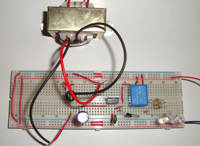
In this emergency light circuit, when the Power goes OFF, the emergency light activates automatically. We have used four bright white LEDs, more LEDs can be added to produce more light considering that total current consumption should not exceed the supply current. Ultra bright white LED consumes 3v and 20mA current.

See here the full article with circuit diagram: emergency light circuit


Friday, 21 August 2015

Battery Monitor Circuit Diagram


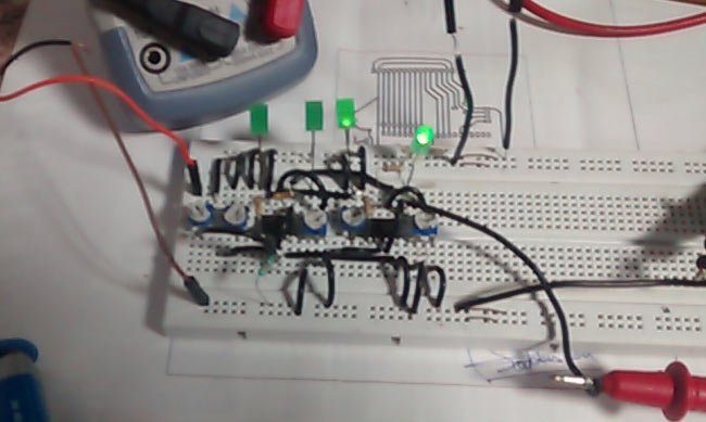
Sometimes we face a common problem when making any project related to battery or power supply - we don’t know about battery is charged or discharged. To test battery there is one common method which is using voltmeter that is available in the Multimeters. But here we have developed this battery monitor circuit to test the battery charging status. In this circuit we can easily test batteries by connecting it with the circuit. Here some LEDs are used for showing battery status.
Check out more details here: Battery Monitor Circuit


Tuesday, 2 June 2015

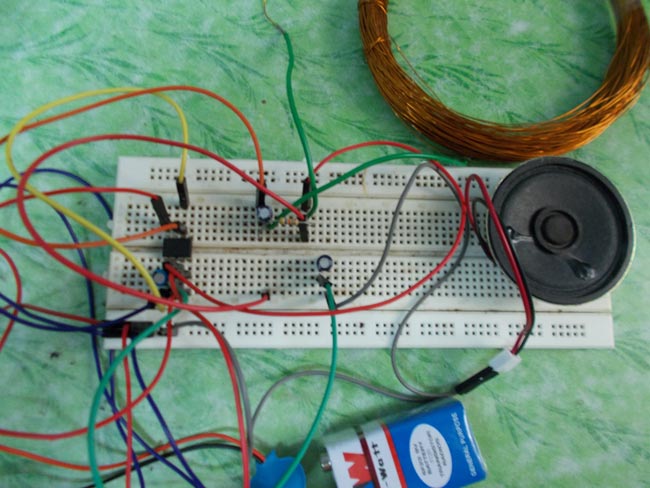
A Simple DIY Metal Detector without using Microcontroller

A metal detector is a device which detects metallic objects. They are commonly used for security purposes on airports, railway stations, malls, etc to prevent entering metal objects like Arms into the premises. 

Designing a metal detector is not that difficult and you can design one simple metal detector circuit without using any microcontroller and by merely using commonly used 555 timer IC. 

This circuit works on 9v DC power supply and uses a copper coil to detect the metal objects. You can find the schematic diagram and detailed explanation of concepts used in this circuit here:


Wednesday, 27 May 2015

Make a Simple Touch Switch Circuit using IC 555


Here is a simple touch switch circuit made using 555 timer IC as a monostable vibrator. We have added two touch pins in the circuit. When the circuit is connected properly, upon touching the "pins", it will glow the LED connected with the circuit. This LED will remain glowing till the trigger is present, and once the trigger is removed LED turns off. 

To make this circuit, find here the touch switch circuit diagram and a detailed explanation of the working of this circuit.

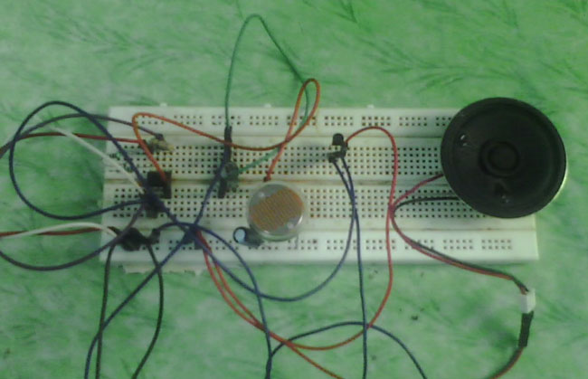
Dark Detector Circuit Diagram using LDR and 555 Timer IC


Dark detector is an application which detects the light in surrounding with the help of a light dependant resistor (LDR) or also known as photo resisotrs. In this project, a square wave generator is created using 555 timer IC based astable multivibrator, and a LDR is interfacing with it. When there is no light in surrounding, or in this case when room light is switched off, the resistance of LDR is increased which makes the LED glows which is connected with the output IC of circuit.


Check out the circuit diagram of dark detector and explanation at Circuit Digest.