Showing posts with label SIM800L. Show all posts

Friday, 13 March 2026

DC Motor Speed Control Using GSM with Arduino – SMS-Based Motor Control

DC Motor Control Using GSM

Automation and remote control systems are becoming increasingly important in modern engineering. In many situations, operating machines manually is not always practical, especially in large industrial setups, agricultural fields, or remote locations. Remote control technologies help solve this problem by allowing devices to be operated from a distance without direct human interaction.

In this project, we build a DC motor speed control using GSM and Arduino. Instead of controlling the motor with physical switches, the motor can be operated remotely using SMS commands sent from a mobile phone. The Arduino receives these commands through a GSM module and controls the motor accordingly.

Components Required

This project uses several commonly available electronic components:

  • Arduino Uno
  • SIM800L GSM Module
  • L298N Motor Driver
  • DC Motor
  • Logic Level Shifter
  • Breadboard
  • Jumper Wires
  • External Power Supply
  • Arduino IDE
Components Required for the DC Motor Control Using GSM

The Arduino Uno acts as the main controller that processes incoming SMS commands and sends control signals to the motor driver. The SIM800L GSM module receives SMS messages from the user’s phone and forwards them to the Arduino. The L298N motor driver is responsible for controlling the speed and direction of the DC motor.

Because the GSM module and Arduino operate at different voltage levels, a logic level shifter is used to ensure safe communication between the two devices.

Circuit Overview

Circuit Diagram of DC Motor Control Using GSM

The circuit connects the Arduino, GSM module, motor driver, and motor together to create a complete control system.

The GSM module communicates with the Arduino through serial communication. When an SMS message is received, the module sends the message data to the Arduino. Since the SIM800L operates at a lower voltage level than the Arduino, a level translator is used to convert the signals safely.

The Arduino processes the received command and sends control signals to the L298N motor driver. The driver then supplies the required current to the motor and determines its direction and speed.

Motor direction is controlled through two input pins on the motor driver, while motor speed is controlled using Pulse Width Modulation (PWM) from the Arduino. A separate power supply is usually required for the motor and GSM module to ensure stable operation.

All components share a common ground connection, which is essential for proper communication between devices.

How GSM-Based Motor Control Works

The working principle of this system is simple and efficient.

When the circuit is powered on, the Arduino and GSM module are initialized. The GSM module connects to the mobile network and waits for incoming SMS messages. Meanwhile, the Arduino continuously monitors the serial interface for new data from the GSM module.

The user sends an SMS command from a mobile phone to control the motor. Each message contains a predefined command that represents a specific motor action.

For example:

  • FWD200Rotate the motor forward at speed level 200

  • REV150Rotate the motor in reverse at speed level 150

  • STOPStop the motor immediately

When the GSM module receives the SMS, it forwards the message content to the Arduino through serial communication. The Arduino reads the message and checks whether it matches one of the predefined commands.

If the command indicates forward rotation, the Arduino sets the input pins of the motor driver accordingly so the motor rotates in the forward direction. If the command indicates reverse rotation, the logic signals are reversed to change the direction.

For speed control, the Arduino generates a PWM signal on the enable pin of the motor driver. By changing the PWM duty cycle, the motor speed can be increased or decreased smoothly.

Using this method, the motor can be controlled remotely from anywhere within GSM network coverage.

Real-World Applications

GSM-based motor control systems have several practical applications.

  • Automated gates
  • Security barriers
  • Home automation systems 

Because GSM communication does not require internet connectivity, the system works reliably even in areas with limited internet access.

The DC motor speed control using GSM and Arduino project demonstrates a practical method for remotely controlling motors using SMS commands. By combining an Arduino Uno, SIM800 GSM module, and L298N motor driver, the motor’s speed and direction can be controlled without physical interaction.

This project also introduces important concepts such as GSM communication, PWM-based speed control, serial interfacing, and motor driver operation. With small modifications, the system can be expanded to control multiple motors or integrated into larger automation systems.

Overall, this project provides a simple and effective solution for remote motor control in real-world applications. 

https://circuitdigest.com 

Robotics Projects |Arduino Projects | Raspberry Pi Projects|

Wednesday, 3 September 2025

Raspberry Pi Pico GPS Tracking Project with SIM800L & Neo-6M – Step by Step Guide

Cellular GPS Tracker with Raspberry Pi Pico


The Raspberry Pi Pico makes it easy to create your own real-time GPS tracking system. With just a few parts and some basic programming, you can build a fully functional IoT GPS tracker thanks to reasonably priced GPS and GSM modules.

We'll demonstrate how to construct a Raspberry Pi Pico GPS tracker in this tutorial using:
  • Neo-6M GPS module to gather location data in real time,
  • cellular communication using the SIM800L GSM module, and
  • Data can be sent to the cloud and shown on an interactive map using the GeoLinker API.


After following this tutorial, you will have a GPS tracker that can record and send real-time location updates, even with offline buffering in case of network outages.

Components Required

Component

Description

Quantity

Raspberry Pi Pico / Pico W

Microcontroller (RP2040)

1

SIM800L Module

GSM/GPRS module for internet access

1

Neo-6M GPS Module

For GPS data Collection

1

GPS Antenna

External GPS antenna with SMA/UFL

1

GSM Antenna

External GSM antenna

1

LED

Red, Yellow, Green

3

SIM

2G Capable SIM (Airtel)

1

Jumper Wires, Breadboard

For prototyping

as needed


How Does It Work?

Pico GPS Tracker concept


  • Neo-6M GPS Module picks up latitude & longitude from GPS satellites and sends them as NMEA sentences.
  • Raspberry Pi Pico reads these values over UART and parses them.
  • SIM800L GSM Module transmits this data to the internet using HTTP POST requests.
  • GeoLinker Cloud API stores the location data and plots it on a real-time map.
  • If the GSM connection drops, data is stored offline and automatically synced once the network is back.

This way, no GPS point is lost even in areas with weak coverage.

Applications of Raspberry Pi Pico GPS Tracker

Pico GPS Tracker with Offline Data Sync

This tracker can be adapted for many real-world uses:
  • Vehicle Fleet Tracking – monitor cars or delivery vans in real-time.
  • Asset Tracking – keep an eye on shipments, parcels, or equipment.
  • Pet Locator – attach it to a collar to track pets.
  • Bike/Scooter Tracking – prevent theft and track movement.
  • Emergency Alert System – send SOS + live location on button press.
Building a Raspberry Pi Pico GPS Tracker, SIM800L, and Neo-6M GPS is not only affordable but also highly customizable. The GeoLinker library removes most of the complexity, letting you focus on logic instead of low-level AT commands.

Sunday, 7 April 2024

Troubleshooting Guide: Interfacing SIM800L with Arduino

If you've ever worked with the SIM800L module (Arduino GSM), you know it's a versatile tool for a variety of projects, from making calls to sending SMS and accessing the internet via GPRS. However, like any tech, it has its quirks. In this article, we'll guide you through interfacing the SIM800L with Arduino and offer troubleshooting tips to ensure smooth operation. Plus, we'll touch on our experience with the SIM800L on ESP32 if you're curious.


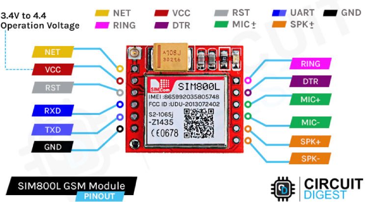
Understanding SIM800L Module Pinout:

The SIM800L module, a GSM/GPRS module, features various pins serving distinct functions critical for its operation. Among these pins, VCC provides the power supply, while GND serves as the ground connection. TX and RX facilitate data transmission and reception, enabling communication with other devices. Understanding the pinout is essential for correctly connecting the module to other components in the system.


Powering the SIM800L GSM Module:

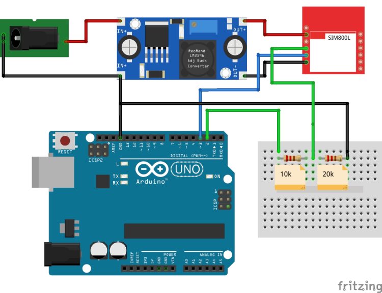
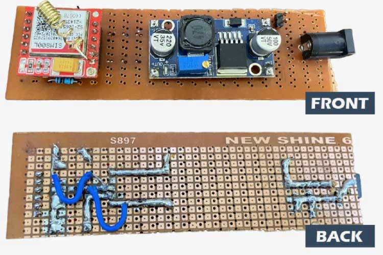
Powering the SIM800L module requires a stable power supply within the range of 3.7V to 4.2V. Achieving this can be accomplished using a buck converter with a minimum current capacity of 2A or a 3.7V Li-ion battery. Additionally, adding a capacitor between VCC and GND can enhance power stability, although it's not mandatory for basic functionality.


Interfacing SIM800L with Arduino UNO:

Interfacing the SIM800L with an Arduino UNO necessitates addressing voltage compatibility issues. While the SIM800L operates at 3.3V, the Arduino UNO internally operates at 5V. To bridge this voltage discrepancy safely, a voltage divider calculator is typically employed, utilizing resistors to generate a 3.3V signal from the Arduino's 5V output.


Troubleshooting SIM800L Issues:

Common issues encountered with the SIM800L module include challenges with SIM card detection and network connectivity. The LED indicators on the module offer valuable insights, such as network status, aiding in the troubleshooting process. Steps for troubleshooting involve verifying correct SIM card insertion, ensuring a stable power supply, and checking for adequate network coverage.


SIM800L AT Command Testing:

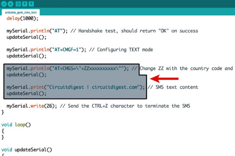
AT commands are instrumental in communicating with the SIM800L module and executing various functions. By uploading an SIM800L AT command test program to the Arduino, direct communication with the module is established. Sending AT commands and interpreting the responses allows for the verification of the module's responsiveness and functionality.


Sending SMS and Making Calls:

Upon confirming the responsiveness of the SIM800L module, exploring its features such as sending SMS and making calls becomes feasible. Sample Arduino code is available for executing these actions, accompanied by detailed explanations of each step in the process. These functionalities broaden the scope of potential applications, enabling communication capabilities within projects.


Conclusion:

Mastering the intricacies of the SIM800L module empowers individuals to leverage its capabilities effectively in various projects. Understanding the module's pinout, power requirements, and troubleshooting techniques facilitates overcoming challenges that may arise during implementation. Furthermore, exploring additional projects, such as SMS-based vehicle tracking and forest fire warning systems, fosters ongoing learning and innovation in utilizing the SIM800L module.