Showing posts with label Innovation. Show all posts

Thursday, 16 May 2024

Calculate the Free-Running Frequency of Astable Multivibrators


Astable multivibrators, a fundamental component in electronics, operate continuously without external triggering, making them essential for generating periodic signals in various electronic devices. This article explores the calculation of the free-running frequency of astable multivibrators, shedding light on their functionality, applications, and significance.


What is an Astable Multivibrator?


An astable multivibrator is an oscillator circuit that alternates between its two unstable states without external triggering. Unlike monostable and bistable multivibrators, astable circuits lack a stable state, earning them the moniker of "free-running oscillators." They find applications in generating clock pulses, timing circuits, and light flashers, among others.

How Astable Multivibrator Works


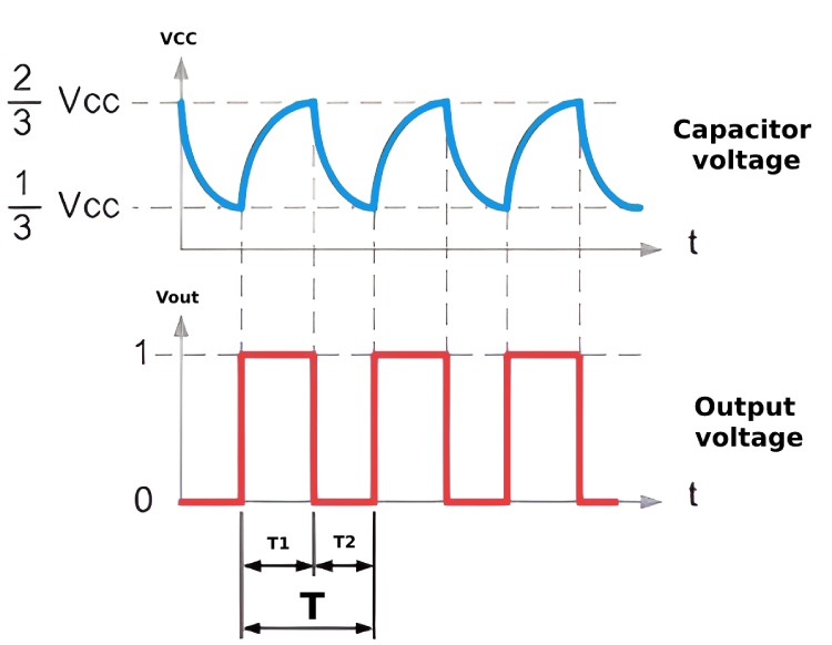
The operation of an astable multivibrator hinges on the charging and discharging cycles of capacitors within the circuit. Typically consisting of two amplifying elements in a feedback loop, such as transistors or operational amplifiers, the circuit's timing intervals are determined by the values of capacitors and resistors. This continuous switching between states produces a square wave output, essential for digital circuits.


Basic Astable Multivibrator Circuit


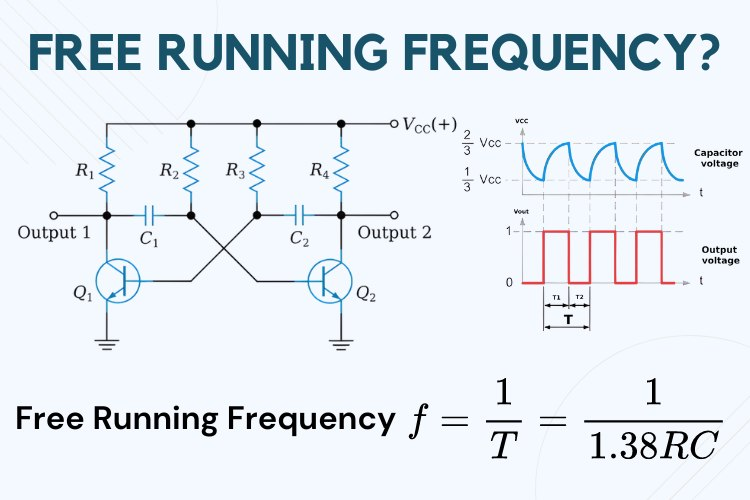
Constructed using transistors, resistors, and capacitors, a basic astable multivibrator circuit comprises two amplifiers arranged with regenerative feedback. The cycling between conducting and cut-off states of the amplifiers generates oscillations, with resistor-capacitor pairs determining timing intervals.


Calculating Free-Running Frequency


The free-running frequency, representing the oscillation rate of an astable multivibrator, is calculated using the formula: f = 1 / (1.38 * R * C), where R is resistance in ohms and C is capacitance in farads. For symmetrical output waveforms, where R2 = R3 and C1 = C2, the time period (T) simplifies to T = 1.38 * R * C. This frequency calculation enables designers to tailor multivibrator behavior to meet specific project requirements.


Applications and Importance


Astable multivibrators find widespread use in electronics, serving in pulse generation, timers, LED flashers, and alarm circuits. Their versatility and simplicity, coupled with the ability to adjust the free-running frequency by tweaking component values, make them indispensable in both amateur and professional electronic projects. The adaptability of astable multivibrators underscores their utility and relevance in modern electronics.


In conclusion, understanding the calculation of the free-running frequency of astable multivibrators provides valuable insights into their functionality and applications, empowering electronics enthusiasts and professionals alike to harness their potential in diverse projects.


Thursday, 9 May 2024

"How to Create Animated Eyes Using Arduino and OLED Displays?


Are you interested in making your own robots come to life with expressive eye animations? If you've been scouring the internet for ways to do this using Arduino and OLED displays but feel overwhelmed by all the information out there, don't worry! We've got you covered with a simple guide (
Arduino OLED Eyes)  to get you started.


What You'll Need


To begin, gather these basic components:


  • Arduino UNO

  • OLED Display (the small, square kind)

  • Breadboard

  • Jumper Wires (the male-to-male kind)

  • USB Cable for Programming


Setting Up the Circuit

First things first, let's connect the OLED display to the Arduino UNO. We'll use a special way of talking between them called the I2C protocol. This just means we'll connect some wires between the Arduino and the display. Also, remember that the OLED display with Arduino needs a special amount of power, so we'll connect it to a specific spot on the Arduino.


Exploring Different Eye Animations

Now comes the fun part – making the eyes move! We've found five different ways people have done this, and each has its own special features.


Option 1: Eye Animation by Intellar

Introducing a repertoire of eye expressions including Normal, Sleep, and Smile, Intellar's approach emphasizes simplicity and ease of use. With functions for adjusting eye position and size, it's ideal for projects requiring basic yet effective animations.


Option 2: Animated Eye by SpiderMaf

SpiderMaf's creation adds a human touch with customizable eye size and position. Compact and efficient, this method employs circles and pupils for precise eye movements, catering to projects seeking a more lifelike appearance.


Option 3: Akno by AbdulsalamAbbod

AbdulsalamAbbod's Akno offers a wide range of expressions, making it perfect for robotic projects. While lacking human-like characteristics, its versatility across various display types makes it a lightweight yet functional choice for hobbyist robots.


Option 4: OLED Moving Eyes by Vinny

Vinny's approach utilizes bitmap images for eye animations, enabling limitless customization. While offering extensive expression sets, memory consumption poses a challenge, restricting its compatibility with Arduino UNO due to space constraints.


Option 5: Robotic Eye Animations by Picaio

Picaio's method stands out with realistic eye movements and a diverse range of expressions. By optimizing bitmap usage, it achieves versatility without compromising on memory. Although slightly complex, it caters to projects demanding nuanced animations.


Now that you know the basics of creating animated eyes with Arduino and OLED displays, it's time to start experimenting! Whether you're building a simple robot or a complex machine, adding expressive eyes will bring your creation to life. So, grab your Arduino and get ready to make some eyes that sparkle with personality!


Wednesday, 8 May 2024

Design Tips and Troubleshooting Guide for the DRV8837

 The DRV8837, a robust N-channel MOSFET-based H-bridge DC motor driver, offers efficient control over DC motors and similar inductive loads. Its internal charge pump ensures seamless operation by generating the required gate drive voltage.


Alternatives:


DRV8837C or DRV8838 can serve as alternatives, with DRV8837C limited to 1A current handling capacity.

Other alternatives include L293D, L298, TB6612FNG, DRV8833, MAX1508, TA6586, DRV8871, MAX1919, and L9110.


Applications:


Robotics, printers, motorized vehicles, toys, solar tracking systems, and DIY projects benefit from the versatile motor control capabilities of the DRV8837.

Its compact footprint and robust features make it suitable for a wide range of applications requiring precise and efficient motor control, offering flexibility and reliability in diverse projects.


Key Design Considerations


Power Supply Recommendations: Incorporating appropriate local bulk capacitance is essential for motor-drive system design. This capacitance should align with factors such as the highest current demands, power-supply capability, and acceptable voltage ripple.

Layout Guidelines: When laying out the PCB, attention should be given to the placement of the VM and VCC pins. Bypassing these pins to ground using low-ESR ceramic capacitors, placed as close as possible to the respective pins, helps minimize parasitic inductance and ensures efficient operation.


Troubleshooting Tips for Seamless Operation


1. Overheating and Circuit Resetting:

Voltage spikes or excessive current demands may cause overheating or circuit resetting. Adding capacitors to suppress voltage spikes and ensuring proper bulk capacitance can mitigate these issues.


2. Non-functionality or Poor Performance:

Check all connections to ensure proper configuration and alignment with motor specifications. Mismatches in voltage or current ratings can lead to non-functionality or subpar performance.


3. Motor Jerking or Inconsistent Operation:

Verify that the voltage and current ratings of the motor align with the DRV8837's specifications. Additionally, adding a 0.1µF capacitor parallel to the motor pins can help reduce noise and ensure smoother operation.


By prioritizing design optimization and adhering to troubleshooting best practices, users can leverage the full potential of the DRV8837 in various applications. Understanding design considerations and addressing common issues empowers users to achieve seamless operation and maximize the efficiency of their motor control systems. For more technical details, refer to the DRV8837 datasheet.


Thursday, 11 April 2024

Build Your Own Fire Fighting Robot with Arduino: A Step-by-Step Guide

 Fires can be devastating, but with advancements in robotics, we can create innovative solutions like the Fire Fighting Robot using Arduino. In this guide, we'll show you how to build a Fire Fighting Robot using simple components and Arduino. This project is a great starting point for anyone interested in robotics and automation.


What You'll Need


Gather these materials to get started:

  • Arduino UNO

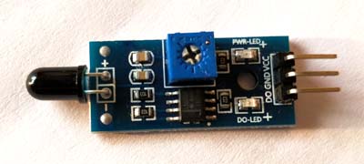
  • Fire or Flame sensors (3)

  • SG90 Servo Motor

  • L293D Motor Driver module

  • Mini DC Submersible Pump

  • Small Breadboard

  • Robot chassis with motors and wheels

  • Small can (for water container)

  • Connecting wires


How the Fire Fighting Robot Works


Our robot uses Arduino and flame sensors to detect fires. When it senses a fire, it calculates the fire's direction using sensor data and moves towards it with motor control. Once close to the fire, the robot activates a mini water pump mounted on a servo motor to spray water and extinguish the flames.


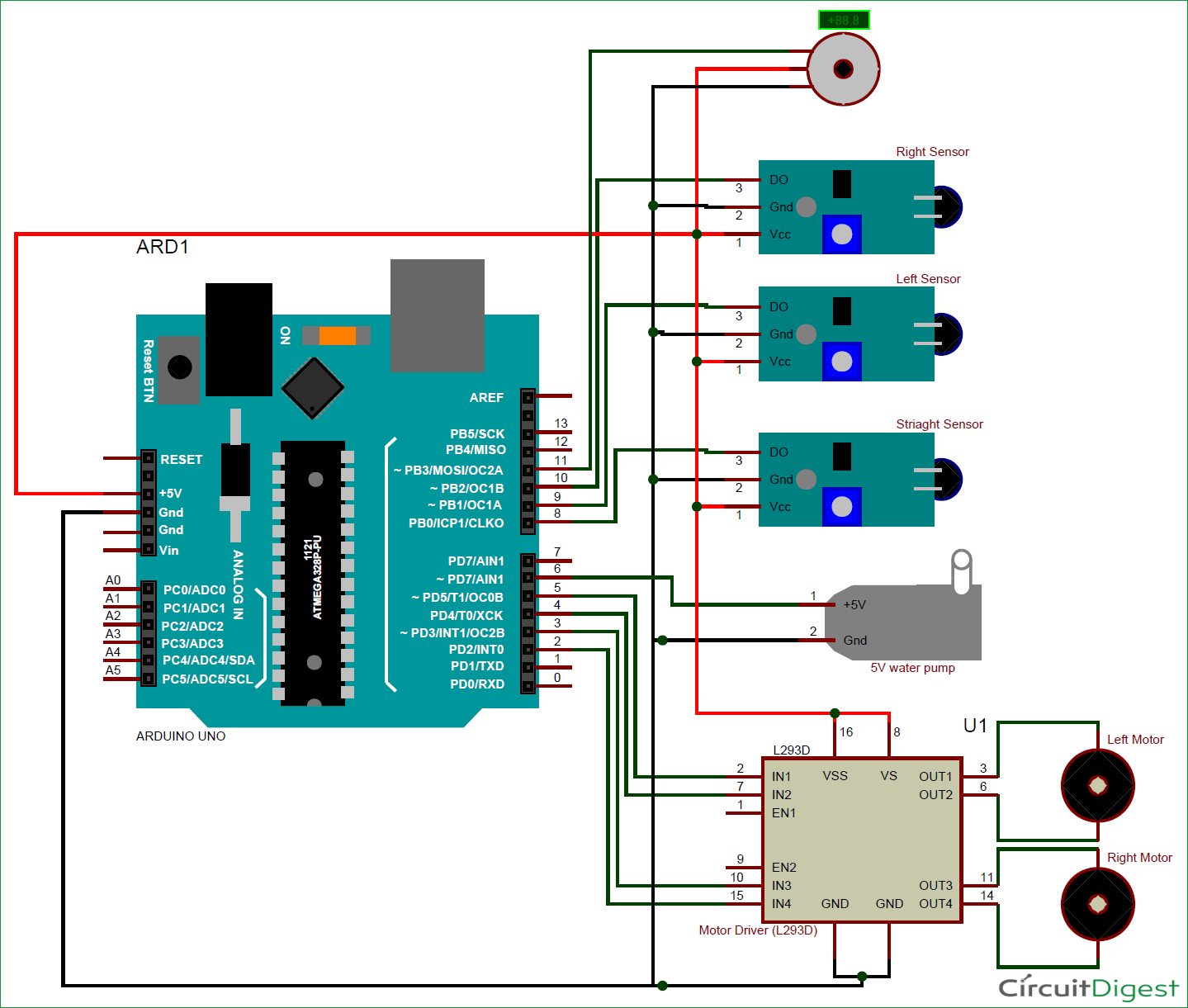
Follow the circuit diagram to assemble your Fire Fighting Robot. The connections are simple and can be adjusted based on your specific robot chassis and pump setup.


Use the provided Arduino code to control the robot's movements and water spraying. Customize the code to fine-tune the robot's behavior based on your preferences.


Testing and Deployment


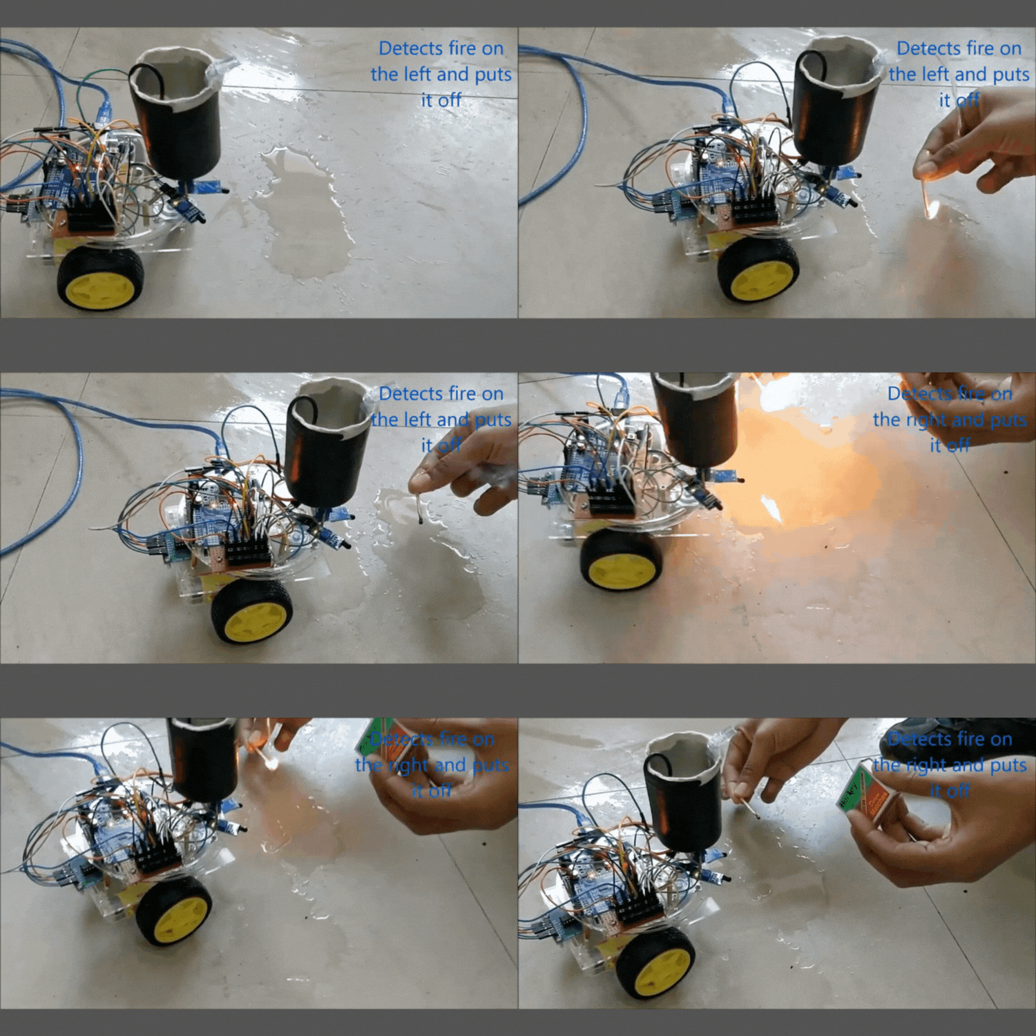
Before putting your robot to work, test each component to ensure everything functions correctly. Once assembled, watch as your robot detects fires and springs into action to extinguish them with precision.


Conclusion


Building a Fire Fighting Robot with Arduino is not just a fun project—it's a meaningful introduction to the world of robotics. Let's use technology to improve safety and protect lives from the dangers of fire.


Explore more robotics projects and share your experiences in the comments or forums. 


Wednesday, 27 March 2024

Building a POV Display: Showing Images and Animations with LEDs and ESP32


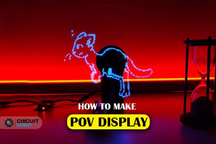
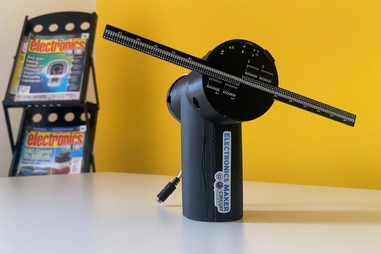
The Persistence of Vision (POV) Display project is about creating a visual illusion using LEDs mounted on rotating arms. This illusion tricks our eyes into seeing continuous motion, similar to how frames in a movie create the impression of movement.


We chose the ESP32 module as the brain of our display because it's affordable, easy to find, and powerful enough to handle the task. Each rotating arm has 64 LEDs, giving us a total display resolution of 128 pixels. This resolution strikes a good balance between image quality and simplicity.


The circuitry controls how the LEDs light up as the arms rotate. We use components like shift registers, voltage regulators, and Hall effect sensors to manage power, LED activation, and synchronization with the rotation speed. Custom PCBs help organize and connect all the components neatly. Working with Viasion Technology, a reliable PCB manufacturer, ensures that our boards are of high quality and meet our project's needs.


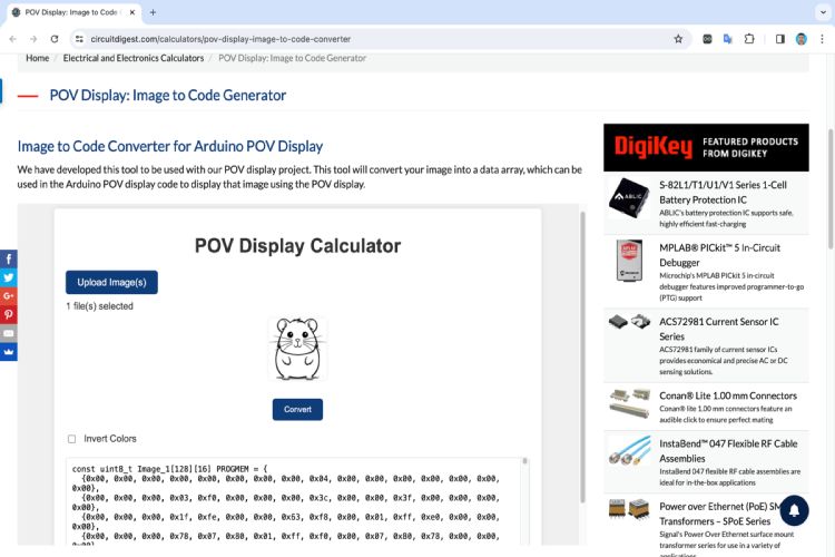
Converting images (image converter tool) for display involves transforming them into a format suitable for the rotating motion. This optimization improves storage efficiency and refresh rates, resulting in smoother animations. Our Arduino code controls everything, from animations to image rendering. It ensures that the LEDs light up at the right times to create captivating visuals. By using interrupts and careful calculations, the code syncs perfectly with the display's rotation.


Overall, our POV Display project is a fun exploration of visual illusions and technology. By following our detailed instructions and using the provided resources, anyone can build their own POV display and enjoy the magic of motion.