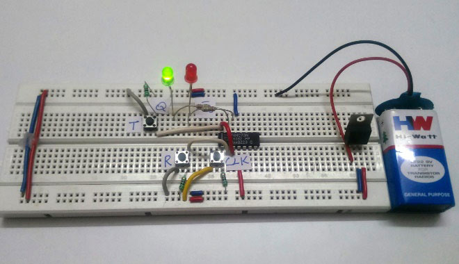
Flip-flops are basic building blocks in digital electronics that work as simple 1-bit memory devices. In electronics Flip-Flop is "A bistable device with synchronous inputs that changes state only at specified transitions of a clock signal" (IEEE Standard 91/1984)". Unlike regular logic gates that respond instantly to inputs, flip-flops can store a value, either 0 or 1, and keep it until something changes it, usually through an input signal and a clock pulse.
Because of this ability to hold information, they’re used in many sequential circuits like counters, registers, and parts of memory in microprocessors. The following tutorial will give you a complete understanding of Flip-Flops in Digital Electronics.
Difference Between Latch and Flip-Flop
A latch is level-triggered, meaning its output changes as long as the input is active. A flip-flop is edge-triggered, updating its output only on a specific clock edge (rising or falling).
Transistors → Logic Gates → Latches → Flip-Flops
Types of Flip Flops in Digital Electronics
- SR Flip-Flop: This is the simplest type of flip-flop that uses Set (S) and Reset (R) inputs to store a bit. It’s great for basic memory storage, but it gets a bit tricky when both inputs are active at the same time.

- D Flip-Flop: Captures the value present at its D input when a clock pulse occurs, and this value is maintained as the output until the next clock pulse. This characteristic makes the D flip-flop a fundamental building block in registers, shift registers, and various other memory devices.

- JK Flip-Flop: Think of it as an improved version of the SR flip-flop that avoids the “invalid” state issue. It can toggle, set, or reset based on its J and K inputs and is very versatile in counters.

- T Flip-Flop: Toggles the output on each clock cycle when T is high. It is particularly useful in applications like counters and control circuits.

Applications of Flip-Flops
- Registers
- Counters
- Finite State Machines (FSMs)
- Pipeline stages
Understanding flip-flops is crucial for anyone interested in digital electronics, as they form the basis for more complex sequential circuits and systems.
For a more detailed explanation and practical demonstrations, refer to the full article on Circuit Digest.: Flip-Flop in Digital Electronics: Types, Truth Table, Logic Circuit and Practical Demonstration

.jpg)