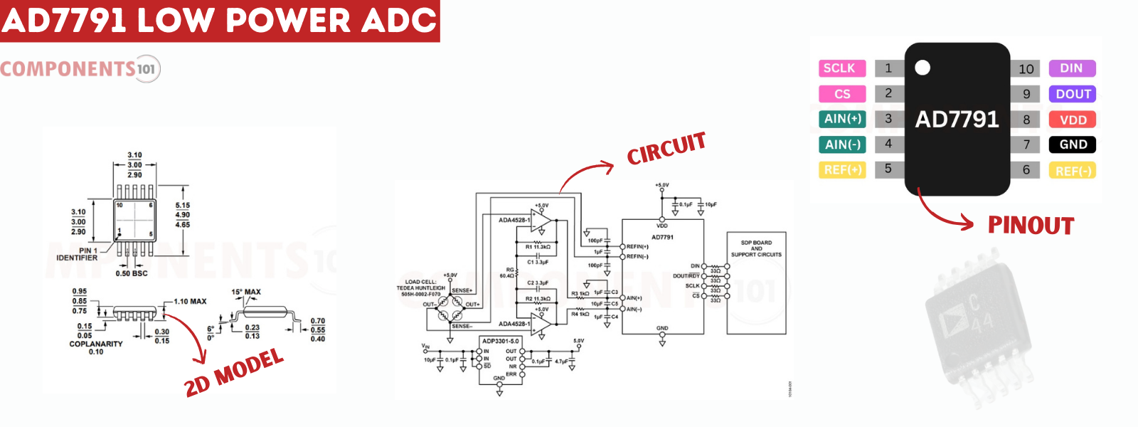
The AD7791 is a 24-bit sigma-delta analog-to-digital converter (ADC) developed by Analog Devices, known for its low-power and low-noise characteristics. It is widely employed in precision measurement applications due to its exceptional resolution and noise performance. Notably, the AD7791 incorporates an internal clock, eliminating the need for an external clock signal. Users can program the output data rate from 9.5Hz to 120Hz, offering flexibility in data acquisition speed.
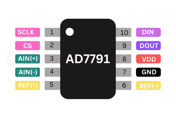
Operating at a 3V supply, the AD7791 consumes a mere 225uW, making it suitable for battery-powered devices. It communicates with microcontrollers or digital systems via a serial interface and is available in a compact 10-pin MSOP package.
Key Features:
Input voltage range from -2.5V to 5.25V
Low current consumption: 75 μA (maximum)
RMS noise: 1.1 μV at 9.5 Hz update rate
Integral nonlinearity: 3.5 ppm typical
Simultaneous rejection of 50 Hz and 60 Hz noise
Internal clock oscillator
Rail-to-rail input buffer
VDD monitor channel
Temperature range: -40°C to +105°C
Troubleshooting Tips for AD7791:
Unstable Performance or Noise Issues: Ensure stable power supply and use bypass capacitors to prevent noise and disturbances.
No Signals from the IC: Verify correct power supply levels and check all connections, including SPI lines and analog inputs.
SPI Communication Problems: Confirm hardware connections and review programming details like bit order and clock phase for SPI communication.
Design tips for AD7791
How to minimize noise while using AD7791?
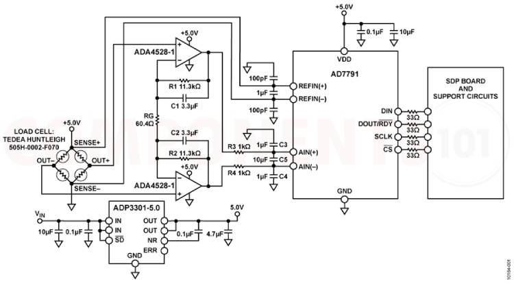
Use 10 µF tantalum capacitors in parallel with 0.1 µF capacitors to decouple VDD to GND. Place decoupling components as close as possible to the device for optimal performance. Decouple all logic chips with 0.1 µF ceramic capacitors to DGND.
Is the ADP7791 sensitive to ESD?
Yes. The performance and working of the IC are well affected by ESD.
How to order ADP7791?
You can check with your supplier with the following part numbers, AD7791BRM, AD7791BRMZ, AD7791BRM-REEL and AD7791BRMZ- REEL. These are all 10 MSOP packages, the only difference is how they are supplied and their markings.
What are the design considerations when designing a PCB using AD7791?
When designing a PCB for the AD7791, it's crucial to separate the analog and digital sections to prevent interference. Employ a minimum etch technique for ground planes to achieve effective shielding against noise. Connect the AD7791's GND pin to the AGND plane and carefully plan current paths to minimize signal disturbances. Keep digital and analog signals segregated to reduce potential noise and interference. Ensure power supply lines are wide to provide low impedance paths and minimize glitches. Shield fast-switching signals like clocks to prevent noise radiation. Avoid crossing digital and analog traces, and orient traces on opposite sides of the board at right angles to minimize feedthrough effects. While a microstrip technique is optimal, it may not be feasible for double-sided boards. In this approach, ground planes are on the component side, with signals on the solder side, optimizing signal integrity and minimizing noise.
The AD7791 is notable for its use in applications such as smart transmitters, battery-powered devices, portable instrumentation, sensor measurement, temperature and pressure measurement, weight scales, and 4 to 20 mA loops.
The device's performance can be optimized by following specific design considerations, such as proper decoupling, PCB layout considerations, and adherence to ESD protection measures. Additionally, designers can choose from various package options based on their project requirements, including AD7790 and AD7792, as alternatives within the same product family HX711, MCP3008, ADS1115, ADC0804, MCP3301.
For more details, refer to the AD7791 datasheet and technical resources.

.png)