Showing posts with label electronics circuits. Show all posts

Wednesday, 4 March 2026

Reverse Polarity Protection Using MOSFET: Guard Your Circuit the Smart Way

Reverse Polarity Protection Using P-Channel Mosfet

You've just finished assembling an electronics project and you're ready to power it up - only to realize the battery might be connected backwards. In that single instant, hours of careful work can be destroyed. Reverse polarity is one of the most common causes of circuit failure, and without protection, it causes immediate component damage, permanent IC failure, or worse, thermal runaway. The good news is that a Reverse Polarity Protection Circuit Using MOSFET can prevent all of that with near-zero efficiency penalty.

Why a Diode Alone Isn't Enough

Diode Based Reverse Polarity Protection Circuit Diagram

The classic fix is simple: place a diode in series with the positive rail. When polarity is correct, it conducts. When reversed, it blocks. It works - but it comes with a hidden cost.

Every forward-biased diode drops approximately 0.7 V and converts that energy directly into heat. In a 12 V system drawing 500 mA, that's 0.35 W of continuous loss and a 5.8% voltage penalty - every second the circuit is powered. For battery-operated or low-voltage devices, that's a tax you simply cannot afford.

The MOSFET Solution

A P-channel MOSFET placed in series with the positive supply line solves the same problem at a fraction of the cost. Here's why it works so elegantly.

When the supply is connected correctly, the gate is pulled to ground through a resistor while the source sits at supply voltage. This makes VGS negative, which turns the MOSFET fully ON - conducting through a channel resistance as low as 0.1 Ω. When polarity is reversed, VGS becomes positive, the MOSFET switches OFF, and current is completely blocked. The internal body diode, oriented against reverse current, provides an additional safety layer.

Running the same numbers - 12 V, 500 mA, RDS(on) of 0.1 Ω - the voltage drop is just 0.05 V and power loss is only 0.025 W. That's a 0.4% efficiency impact compared to the diode's 5.8%. The MOSFET dissipates roughly 14 times less power under identical conditions.

How to Build It

You need just four components: a P-channel MOSFET (IRF9710), a 1N4007 diode, a 1 kΩ gate resistor, and your load.

Place the IRF9710 on a breadboard and identify the Source, Gate, and Drain from the datasheet. Connect the 1 kΩ resistor from Gate to Ground - this pull-down keeps VGS negative under correct polarity. Add the 1N4007 with cathode to Gate and anode to Ground to prevent a damaging reverse gate voltage from appearing during a miswiring event. Finally, connect your load between the Drain rail and GND. Correct polarity powers the load normally. Reversed polarity keeps the MOSFET off and the load completely unharmed.

When to Add a Zener Diode

MOSFET Reverse Polarity Protection with Gate Zener

The basic circuit works well below 20 V. For automotive systems, industrial rails, or any environment with voltage spikes, the gate-to-source voltage can momentarily exceed the MOSFET's ±20 V rating and permanently damage the gate oxide - often with no visible warning.

Adding a Zener diode between Gate and Source clamps VGS to a safe level. It's one extra component, costs almost nothing, and is the difference between a circuit that survives field conditions and one that doesn't.

Choosing the Right MOSFET

P Channel MOSFET Reverse Polarity Protection Circuit Diagram

Five parameters matter when selecting a device. VDS(max) should be at least 1.5 times your supply voltage. VGS(th) must be low enough to switch on fully at your rail - for 3.3 V or 5 V systems, use a logic-level device like the AO3401. RDS(on) should be below 0.1 Ω for currents under 5 A. ID(max) should be at least twice your peak load current. And if your supply exceeds 15 V, include the Zener gate clamp.

A diode protects your circuit but wastes energy doing it. A P-channel MOSFET protects your circuit while barely touching efficiency. For battery-powered gadgets, microcontroller boards, IoT sensors, automotive accessories, or any project where efficiency and reliability both matter, MOSFET-based reverse polarity protection is the right engineering choice - and it costs almost nothing to implement correctly.

For more in depth understanding : Reverse Polarity Protection Using MOSFET | Step By Step Circuit Guide


https://circuitdigest.com 

Robotics Projects |Arduino Projects | Raspberry Pi Projects|

Friday, 21 March 2025

How to use L298N Motor Driver with Arduino?

How to use L298N Motor Driver with Arduino


What is the L298N Motor Driver Module?

The L298N Motor Driver Module is a high power motor driver module for driving DC and Stepper Motors.. It supports motors operating at 5V to 35V and offers features like:

  • Forward & Reverse Motor Control
  • PWM Speed Control
  • Overheating & Overcurrent Protection
  • Separate Power Input for Motors & Logic Control
Circuit Diagram for Interfacing L298N Motor Driver with Arduino


Components Required
Here’s what you’ll need for this project:
  • Arduino Uno
  • L298N Motor Driver Module
  • DC Motor (5V–12V)
  • Power Source (Battery or Adapter)
  • Jumper Wires
Components needed for interfacing the L298N Driver Module with Arduino.

This project explains how to interface the L298N Motor Driver Module with Arduino to control DC motors efficiently. The L298N allows you to regulate motor speed and direction using PWM signals, making it perfect for robotics, automation, and motorized projects. With this tutorial, you'll learn to drive motors forward, backward, and at variable speeds, enabling you to build remote-controlled cars, conveyor systems, and robotic arms.


Sunday, 11 February 2024

Basics of Bipolar Junction Transistors in Electronic Circuits

Transistors are super important in electronic circuits, from basic ones to more complex ones. Bipolar Junction Transistors (BJTs) are a big part of this. They're like switches controlled by electricity. They have three parts: emitter, collector, and base. BJTs control how electricity flows between the emitter and collector based on the electricity sent to the base. They're shown as NPN or PNP symbols, depending on how they're set up inside.


BJTs work like switches or boosters. When you give a little electricity to the base, it lets a bigger flow of electricity from the collector to the emitter, turning the transistor on. They can be set up in different ways—Common Base (CB), Common Emitter (CE), and Common Collector (CC)—and each way affects how they handle electricity. BJTs are good for boosting electricity and turning things on and off quickly, but they use more power and can get hot.

Field Effect Transistors (FETs) are another type, and they work a bit differently. They're good for some things BJTs aren't, like using less power. BJTs are used in lots of circuits, like ones that do math, boost sound, or control time. They come in different packages to fit different needs. Overall, BJTs are a big part of electronics, helping circuits do lots of cool stuff, but they need to be used carefully to avoid problems.

For more detailed information on how Bipolar Junction Transistors (BJTs) work and their applications, you can check out the full article - BJT Transistors: Symbol, Basics, Construction, Working & Applications (components101.com)


Wednesday, 15 July 2015

Timer Circuits

Sometimes we need to create timer circuits in our product and application designs. 555 timer is one of the popular and efficient IC to provide accurate time delays in the circuits. Here is a tutorial which guides you to create different time delays in the circuit using IC 555.


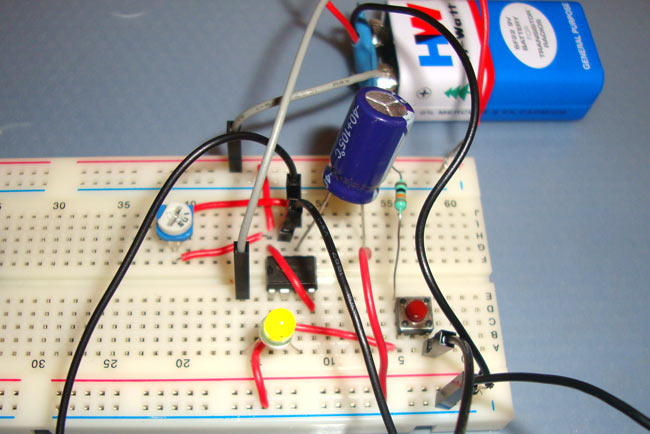
Here 555 IC is configured in monostable mode and by changing different resistor values, different time delay is achieved.

Check out the complete circuit here: 1 minute timer circuit

For more such circuits, check our 555 Circuits section.

Wednesday, 10 June 2015

Make a four way traffic light signal project using IC 555


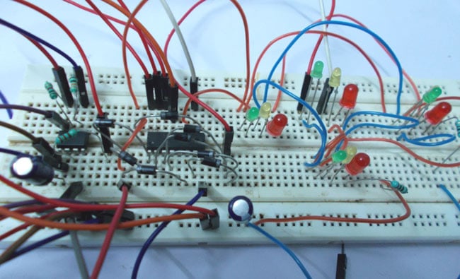
This simple project demonstrates the working of a traffic light signal. It uses a 555 timer IC and a decade counter to build this four way traffic light circuit. 

The concept of this project is very simple. The ten stage DECADE COUNTER have a memory of ten, that means, it can count upto ten pulses. So for every peak at clock, the counter admits it as an event and remembers it. The number of events that counter memorized outputted by corresponding pin.

Visit the link below for complete circuit diagram and explanation of its working.
http://circuitdigest.com/electronic-circuits/four-way-traffic-light-circuit

For more such projects visit our electronics circuit section.