Showing posts with label ElectricalTutorial. Show all posts

Tuesday, 2 June 2026

Building Modern Embedded GUIs with LVGL and Arduino IDE

Arduino LVGL for ESP32 Display

Creating attractive user interfaces for embedded devices used to be a difficult task. Developers often had to manually draw buttons, text, and graphics, making even simple interfaces time-consuming to build. With LVGL (Light and Versatile Graphics Library), creating professional-looking touch interfaces on microcontrollers has become much easier. In this Arduino LVGL for ESP32 Display project, we explore how to build a custom GUI using LVGL and Arduino IDE on an ESP32-C3-based round display board.

What is LVGL?

LVGL is an open-source graphics library designed specifically for embedded systems. It provides ready-made UI components such as buttons, sliders, charts, labels, switches, and animations that can be used to create modern interfaces without building everything from scratch.

You'll find LVGL powering dashboards, smart home controllers, industrial displays, smartwatches, and many other embedded products. Its biggest advantage is that it delivers a smartphone-like user experience even on resource-constrained microcontrollers.

Why Use LVGL with ESP32?

The ESP32 is one of the most popular microcontrollers for display-based projects. When combined with LVGL, it becomes a powerful platform for creating responsive and visually appealing interfaces.

Some key benefits include:

  • Ready-made widgets and UI components
  • Smooth animations and transitions
  • Touchscreen support
  • Cross-platform compatibility
  • Open-source and free for commercial use
  • Support for visual GUI design tools

Instead of manually drawing graphics using libraries such as TFT_eSPI, LVGL lets you focus on designing the user experience.

Hardware Used

ESP32C3-smartwatch-views

For this demonstration, an ESP32-C3 round display development board was used. The board comes with:

  • ESP32-C3 microcontroller
  • 1.28-inch 240×240 round IPS display
  • GC9A01 display driver
  • CST816D capacitive touch controller
  • USB programming interface
  • Battery charging support

The integrated display and touch controller eliminate the need for complicated wiring, making it an ideal platform for learning LVGL.

Setting Up LVGL in Arduino IDE

LVGL-Documentation

Getting started is straightforward. First, install the LVGL library through the Arduino Library Manager. Once installed, visit the official LVGL documentation and browse through the available widgets.

One of the best features of LVGL is its extensive documentation. Every widget includes a live preview and a ready-to-use code snippet. Simply copy the example code and integrate it into your project.

For this tutorial, a simple button and toggle switch example is used to demonstrate how LVGL widgets work.

Creating Your First GUI

After uploading the code to the ESP32, the display shows two interactive buttons.

The first button acts like a standard push button and generates events when pressed. The second button works as a toggle switch. When toggled ON, the screen background changes to white. When toggled OFF, the background returns to dark mode.

This simple example demonstrates one of LVGL's biggest strengths: event-driven UI design. Instead of manually tracking every screen interaction, LVGL provides built-in event handling that makes interface development much easier.

Why LVGL is Better Than Traditional Graphics Libraries

Traditional display libraries focus mainly on drawing graphics. LVGL goes much further by providing a complete GUI framework.

With LVGL, you get:

  • Buttons, sliders, and switches
  • Charts and graphs
  • Built-in animations
  • Touch input management
  • Theme support
  • Responsive layouts

This significantly reduces development time while improving the overall user experience.

If you're building dashboards, smart home controllers, wearable devices, or touchscreen IoT products, learning LVGL is one of the most valuable skills you can add to your embedded development toolkit. By combining the flexibility of Arduino IDE with the power of LVGL and ESP32, you can create professional-grade graphical interfaces that look and feel like commercial products without requiring advanced graphics programming knowledge.

https://circuitdigest.com 

Robotics Projects |Arduino Projects | Raspberry Pi Projects|

Wednesday, 29 April 2026

ESP32-C3 Text-to-Speech Using AI (Cloud-Based TTS)

Text-to-Speech on ESP32-C3 using Wit.ai

Text-to-Speech (TTS) is one of those features that instantly makes any electronics project feel more interactive. But when you try to implement it on a microcontroller, things get tricky. Devices like the ESP32-C3 don’t have the memory or processing power to generate natural speech locally. That’s why this project takes a smarter route - using cloud-based AI to handle the heavy work while the microcontroller focuses on communication and playback.

Why Use Cloud-Based TTS on ESP32-C3?

The ESP32-C3 Dev Module is powerful for IoT, but real-time speech synthesis is still beyond its practical limits. Instead of forcing offline processing, this project ESP32 C3 Text to Speech using AI sends text over WiFi to a cloud service, where speech is generated and streamed back as audio.

This approach keeps the system:

  • Lightweight
  • Scalable
  • Easy to implement

And most importantly, it delivers high-quality, natural-sounding speech without complex hardware.

How the System Works

The workflow is simple and efficient:

  1. ESP32-C3 connects to Wi-Fi
  2. Text input is sent to the cloud API
  3. The cloud service converts text into audio
  4. Audio is streamed back in real time
  5. The ESP32 plays it through a speaker

All the complex steps—text processing, voice modeling, and waveform generation - are handled remotely, allowing even a small device to “speak” clearly.

The AI Engine Behind It

This project uses Wit.ai, a cloud-based platform that provides Text-to-Speech via simple HTTP APIs.

Instead of building your own speech engine, you are just:

  • Send text with authentication
  • Receive audio (MP3/WAV)
  • Play it instantly

The platform also supports multiple voices and languages, making it flexible for different applications.

Hardware Required

ESP32 C3 Text to Speech Components

The setup is minimal and beginner-friendly:

  • ESP32-C3 Dev Module
  • MAX98357A I2S amplifier
  • Speaker (4Ω or 8Ω)
  • Breadboard and jumper wires

The amplifier uses I2S communication, allowing digital audio streaming directly from the ESP32 to the speaker.

Code Logic (Simplified)

Once the hardware is ready, the code handles everything:

  • Connects to WiFi
  • Authenticates using a Wit.ai token
  • Sends text for speech conversion
  • Streams audio and plays it

With the WitAITTS library, most of the complexity is already handled, so you only need a few lines of code to get started.

What Makes This Approach Better

Compared to offline TTS, this method offers:

  • Better audio quality (AI-generated voices)
  • Dynamic text support (any sentence, anytime)
  • Lower memory usage
  • Easy updates without firmware changes

Offline methods, on the other hand, are limited to pre-recorded audio or low-quality synthesis.

Real-World Applications

This setup isn’t just a demo - it can be used in practical projects like:

  • Smart home voice alerts
  • IoT notification systems
  • Talking assistants
  • Accessibility tools
  • Industrial alert systems

Anywhere you need voice output, this method fits well.

Common Issues

A few things to check during setup:

  • No sound → verify amplifier wiring
  • API errors → check your access token
  • Audio distortion → ensure stable power supply

Most problems are hardware or network-related rather than code issues.

This ESP32-C3 Text-to-Speech project shows how combining IoT with cloud AI can unlock features that would otherwise be impossible on small hardware.

Instead of pushing the limits of the microcontroller, it uses the cloud intelligently to deliver high-quality speech with minimal effort.

If you're building interactive IoT devices, adding voice output this way is one of the most practical and scalable solutions available today. 

https://circuitdigest.com 

Robotics Projects |Arduino Projects | Raspberry Pi Projects|

Monday, 20 April 2026

Raspberry Pi Pico Text-to-Speech Using AI (Wit.ai)

Raspberry Pi Pico Text to Speech using AI

Turning text into speech sounds simple - until you try doing it on a microcontroller. Devices like the Raspberry Pi Pico don’t have the processing power or memory to generate natural speech on their own. That’s where this project gets interesting. Instead of forcing the Pico to do heavy work, we let the cloud handle it.

Why This Approach Works

The Raspberry Pi Pico W is great for embedded projects, but it’s not built for audio processing. Generating realistic speech requires complex models and significant memory - something microcontrollers simply don’t have.

So instead, this project uses a cloud-based Text-to-Speech system. The Pico sends text over WiFi to an online service, and that service converts it into speech and sends back audio. The Pico just plays it. Simple, efficient, and practical.

What Powers the Speech?

WitAi Homepage

The project Raspberry Pi Pico Text to Speech using AI uses Wit.ai, a platform developed by Meta that handles speech processing through APIs. You send text via HTTPS, and it returns audio in real time.

This setup gives you:

  • Natural-sounding voice output
  • Support for multiple languages
  • No heavy processing on the Pico

And since everything runs in the cloud, updating voices or features doesn’t require changing your hardware.

Hardware Setup

Rpi Pico WitAITTS Component

The hardware is minimal and beginner-friendly:

  • Raspberry Pi Pico W
  • MAX98357A audio amplifier
  • Speaker (4Ω or 8Ω)
  • Breadboard and jumper wires

The amplifier connects using I2S pins, allowing digital audio from the Pico to be converted into sound through the speaker.

How It Actually Works

The workflow is clean and easy to follow:

  1. The Pico connects to WiFi
  2. You send text (via Serial Monitor or code)
  3. The Pico sends this text to Wit.ai
  4. Wit.ai converts it into speech
  5. Audio is streamed back to the Pico
  6. The speaker plays the sound instantly

What’s nice here is that the audio is streamed, not fully downloaded first. That means faster response and less memory usage.

Code Logic (In Simple Terms)

The program creates a TTS engine, connects to WiFi, and authenticates using a token from Wit.ai.

Then:

  • You set voice, speed, and pitch
  • Send text using a simple function
  • The system handles the rest automatically

It’s mostly plug-and-play once configured.

Where You Can Use This

This project isn’t just a demo. It can actually be used in real applications:

  • Smart home voice alerts
  • Talking IoT devices
  • Accessibility tools
  • Educational kits
  • Notification systems

Once you get the basics working, you can connect it with sensors, APIs, or automation systems.

This project shows how powerful a simple idea can be when done right. Instead of pushing hardware limits, it uses the cloud intelligently.

The result?
A lightweight system that delivers clear, natural speech using minimal components.

If you’re working with microcontrollers and want to add voice output without overcomplicating things, this is one of the cleanest ways to do it.

https://circuitdigest.com 

Robotics Projects |Arduino Projects | Raspberry Pi Projects|

Arduino UNO Q Face Detection Project – A Simple Entry into Edge AI

Arduino UNO Q - Beginners Guide

From blinking LEDs to building full-fledged smart systems, Arduino boards have always been a go-to for makers. Now, things get a serious upgrade with the Arduino UNO Q, a board that blends the simplicity of Arduino with the power of modern computing.

In this you getting started with Arduino UNO Q   project, we explore something that once felt complex - real-time face detection - and make it surprisingly simple using the UNO Q and Arduino App Lab.

What Makes Arduino UNO Q Different?

Arduino UNO and UNO Q With Dimensions

Unlike traditional boards, the Arduino UNO Q isn’t just a microcontroller. It combines a powerful Linux-based processor with a real-time microcontroller. This means it can handle both high-level tasks like AI processing and low-level hardware control at the same time.

In simple terms, you get the best of both worlds:

  • Power for AI and vision tasks
  • Real-time control for sensors and hardware
  • Built-in WiFi and Bluetooth

That’s a big jump from the classic Arduino experience.

Project Idea: Face Detection Made Easy

Setup of UNO Q Web Camera and Laptop

This project uses a USB webcam to detect faces in real time. The UNO Q processes the video feed and highlights detected faces with bounding boxes.

The best part? You don’t need to write complex AI code. Arduino App Lab uses a brick-based system, where you simply connect functional blocks to build your program.

Hardware Setup

The setup is straightforward and beginner-friendly:

  • Arduino UNO Q
  • USB webcam
  • Laptop
  • Type-C hub (for connectivity)

You connect the UNO Q to your laptop using a USB-C hub, plug in the webcam, and you’re ready to go. This setup allows the board to interact with both the camera and the development environment smoothly.

Getting Started with Arduino App Lab

Instead of the traditional Arduino IDE, this project uses Arduino App Lab. It’s a visual programming environment where you drag and connect blocks (called “bricks”) to create applications.

Once the board is connected, you can:

  • Open example projects
  • Load the Face Detector example
  • Run the program instantly

No complicated setup, no deep AI coding required.

Running the Face Detection Program

After loading the example, just hit Run. Within a few seconds, a browser window opens showing the live camera feed.

The system detects faces and draws bounding boxes around them. You’ll also see a confidence score, which tells how accurate the detection is.

You can even tweak detection sensitivity using a slider, making it interactive and easy to experiment with.

Why This Project Stands Out

What makes this project interesting is how it simplifies something advanced. Face detection usually requires frameworks like TensorFlow or OpenCV setup. Here, it’s reduced to a few clicks.

It shows how the UNO Q bridges the gap between:

  • Beginner-friendly electronics
  • Advanced AI-based applications

Real-World Applications

This simple demo opens the door to many practical ideas:

  • Smart surveillance systems
  • Attendance tracking
  • Human-machine interaction
  • AI-based robotics

You can extend this further into face recognition, object detection, or even gesture-based control systems.

The Arduino UNO Q specifications change how we think about Arduino projects. It’s no longer limited to basic electronics - it steps into AI and edge computing without making things complicated.

This face detection project is a great starting point. It’s simple to build, easy to understand, and gives you a glimpse into what modern embedded systems can do.

If you’re someone moving from basic Arduino projects to something more advanced, this is exactly the kind of project that makes that transition smooth.

https://circuitdigest.com 

Robotics Projects |Arduino Projects | Raspberry Pi Projects|


Friday, 9 January 2026

DIY Bluetooth Speaker — Build Your Own Wireless Audio System

diy bluetooth speaker amplifier

Listening to music wirelessly through a Bluetooth speaker is something we all enjoy, but did you know you can build your own DIY Bluetooth Speaker Amplifier at home with just a few affordable electronic parts? This DIY Bluetooth speaker project lets you stream music from your phone or any Bluetooth-enabled device without wires. It’s a fun and practical way to learn about wireless audio, amplification, and basic circuitry while creating a portable speaker you can actually use.

What This Project Is About

In this project, you’ll combine a Bluetooth audio receiver module with a small audio amplifier and speaker drivers to make a compact and budget-friendly wireless speaker system. The Bluetooth module receives audio wirelessly, the amplifier boosts the signal to drive the speakers, and everything runs on a simple power supply like a USB power bank or 5 V adapter.

Components Required

To build your Bluetooth speaker, you’ll need:

  • JDY-62 Bluetooth 4.2 module – Receives audio over Bluetooth
  • PAM8403 amplifier board – Boosts audio signal to drive speakers
  • 2 × 8Ω speakers – Produce sound output
  • 5 V power supply – USB power bank or wall adapter
  • Wires and soldering tools – For connections and assembly
Components Required diy bluetooth speaker amplifier

Components Required diy bluetooth speaker amplifier

These parts are inexpensive and widely available, making this project easy for beginners and hobbyists alike.

How It Works

  1. Bluetooth Audio Reception – The Bluetooth module pairs with your phone or tablet and receives the audio signal wirelessly.
  2. Signal Amplification – The audio output from the Bluetooth module is fed into the PAM8403 amplifier, which boosts the low-level audio signal.
  3. Speaker Output – Amplified audio drives the connected speakers to produce clear sound.
  4. Power Supply – A simple 5 V source powers both the Bluetooth module and amplifier, keeping the system compact and portable.
DIY Bluetooth Speaker Circuit Diagram

When you turn on the system and pair your device, you’ll be ready to enjoy wireless audio instantly.

Why This Project Is Great

  • Affordable and practical - Easy to build for under a small budget.
  • Wireless music - Stream audio from phones and laptops seamlessly.
  • Educational - Learn about Bluetooth modules, audio amplification, and basic electronics.
  • Customisable - Expand with volume controls, battery power, or LED indicators.

Building your own DIY Bluetooth Speaker Amplifier is both fun and rewarding. With just a Bluetooth audio receiver, a tiny amplifier, and a pair of speakers, you can create a wireless audio system that works anywhere. It’s a perfect weekend project for beginners and a great way to dive into practical electronics while enjoying music in style. 

Saturday, 8 June 2024

Understanding Staircase Lighting with Two-Way Switches: A Practical Guide


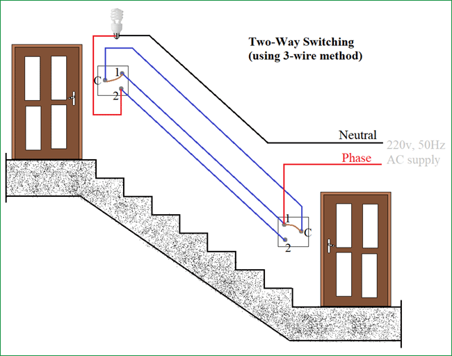
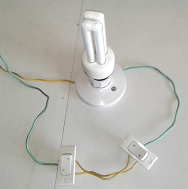
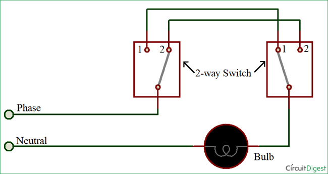
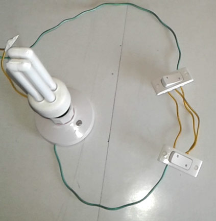
One of the first practical projects young engineers encounter is the staircase lighting setup. This setup uses a 2 way switch wiring, allowing you to control a light from two different locations, ideal for staircases.


Components Required

  1. Two 2-way switches

  2. Bulb

  3. AC supply

  4. Connecting wires


Two-Wire Control Method

This older method connects the live wire to the common terminal of the first switch. The other terminals of both switches are cross-connected. The light connects to the second switch and is neutral. The light is off when switches are in opposite states, similar to an Ex-NOR gate.


Three-Wire Control Method


This modern method short-circuits the common terminals of both switches. One terminal of each switch connects to the live wire, and the other terminal to the lamp. The light is on when switches are in different states, akin to an Ex-OR gate.


Applications

  • Staircases

  • Large rooms with multiple entry/exit points

  • Controlling AC appliances from two locations


This setup provides a simple and effective solution for controlling lights in various scenarios.


For a detailed video tutorial, check out the link below: 2 Way Switch Wiring