Showing posts with label Automation. Show all posts

Tuesday, 11 March 2025

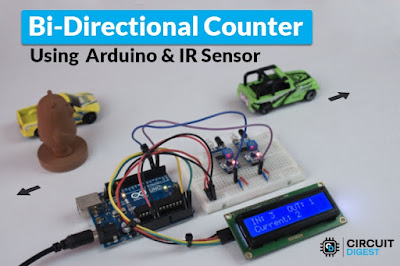
How to Build a Bidirectional Visitor Counter using Arduino

How-to-Build-a-Bidirectional-Counter-Using-Arduino-and-IR-Sensors
What is a Bidirectional Counter?

A bidirectional counter counts objects or people moving in two directions, incrementing the count for one direction and decrementing for the opposite. It is commonly used in:

  • Automatic door entry systems
  • Visitor counters in malls, offices, and stations
  • Industrial conveyor belt monitoring

Components Required

To build this project, you'll need:

  • Arduino Uno
  • IR Sensors (2x)
  • 7-Segment Display or LCD
  • Resistors & Capacitors
  • Jumper Wires & Breadboard
Hardware-Connection-of-Bidirectional-Counter-System-using-IR-Sensors (1)


This project demonstrates how to use the L298N Motor Driver Module with Arduino to control the speed and direction of a DC motor. By leveraging PWM (Pulse Width Modulation) signals, you can achieve precise motion control, making it ideal for robotics, automation, and motorized systems. Whether you're a beginner or an advanced maker, this tutorial will help you understand motor control concepts and apply them to your own projects.

Friday, 10 May 2024

L9110 Motor Driver IC: Design and Troubleshooting Tips

 The L9110 motor driver IC is a cost-effective solution for controlling DC motors in a variety of applications. With its wide input voltage range and bi-directional control capability, it offers versatility and simplicity for hobbyists and engineers alike.


Features of L9110


Low Quiescent Current: Operates efficiently with minimal power consumption.

Wide Supply Voltage Range: Compatible with voltages ranging from 2.5V to 12V.

High Current Output: Capable of delivering up to 800mA continuous current per channel.

TTL/CMOS Compatibility: Easily integrates with digital logic circuits for seamless control.

Built-in Clamp Diodes: Protects against reverse inductive load current for enhanced safety.


Applications of L9110: Robotics, printers, toys, DIY projects.

Alternatives to L9110: L293D, L298, TB6612FNG, DRV8833, MAX1508, TA6586,  DRV8871,MX1919.


Troubleshooting Tips


Circuit Resets: Ensure motor supply voltage is within the rated range and consider adding a capacitor parallel to the motor to mitigate voltage spikes.

Overheating IC: Address issues such as overloading, voltage spikes, or poor heat dissipation by adding capacitors to suppress spikes and ensuring proper ventilation.


Design Considerations


Proper Grounding: Establish a solid ground plane to minimize noise and interference.

Current Capacity: Ensure sufficient track width to handle high currents.

Decoupling Capacitors: Place capacitors close to power pins for efficient noise suppression.

Signal Tracks: Keep signal tracks short and direct for optimal performance.


The L9110 motor driver IC offers a simple and effective solution for controlling DC motors in various applications. With its compact size, versatile features, and ease of use, it's an excellent choice for hobbyists and professionals seeking reliable motor control. For detailed technical specifications and mechanical drawings, refer to the L9110 datasheet available here.


Wednesday, 8 May 2024

Design Tips and Troubleshooting Guide for the DRV8837

 The DRV8837, a robust N-channel MOSFET-based H-bridge DC motor driver, offers efficient control over DC motors and similar inductive loads. Its internal charge pump ensures seamless operation by generating the required gate drive voltage.


Alternatives:


DRV8837C or DRV8838 can serve as alternatives, with DRV8837C limited to 1A current handling capacity.

Other alternatives include L293D, L298, TB6612FNG, DRV8833, MAX1508, TA6586, DRV8871, MAX1919, and L9110.


Applications:


Robotics, printers, motorized vehicles, toys, solar tracking systems, and DIY projects benefit from the versatile motor control capabilities of the DRV8837.

Its compact footprint and robust features make it suitable for a wide range of applications requiring precise and efficient motor control, offering flexibility and reliability in diverse projects.


Key Design Considerations


Power Supply Recommendations: Incorporating appropriate local bulk capacitance is essential for motor-drive system design. This capacitance should align with factors such as the highest current demands, power-supply capability, and acceptable voltage ripple.

Layout Guidelines: When laying out the PCB, attention should be given to the placement of the VM and VCC pins. Bypassing these pins to ground using low-ESR ceramic capacitors, placed as close as possible to the respective pins, helps minimize parasitic inductance and ensures efficient operation.


Troubleshooting Tips for Seamless Operation


1. Overheating and Circuit Resetting:

Voltage spikes or excessive current demands may cause overheating or circuit resetting. Adding capacitors to suppress voltage spikes and ensuring proper bulk capacitance can mitigate these issues.


2. Non-functionality or Poor Performance:

Check all connections to ensure proper configuration and alignment with motor specifications. Mismatches in voltage or current ratings can lead to non-functionality or subpar performance.


3. Motor Jerking or Inconsistent Operation:

Verify that the voltage and current ratings of the motor align with the DRV8837's specifications. Additionally, adding a 0.1µF capacitor parallel to the motor pins can help reduce noise and ensure smoother operation.


By prioritizing design optimization and adhering to troubleshooting best practices, users can leverage the full potential of the DRV8837 in various applications. Understanding design considerations and addressing common issues empowers users to achieve seamless operation and maximize the efficiency of their motor control systems. For more technical details, refer to the DRV8837 datasheet.


Friday, 3 May 2024

TA6586 Bi-Directional DC Motor Driver IC: Design and Troubleshooting Guide


The
TA6586 is a cost-effective bi-directional DC motor driver IC suitable for a wide range of applications, particularly in hobby projects and motor-operated circuits. Offering features such as anti-interference performance, low standby current, and a built-in diode for reverse inductive load current prevention, the TA6586 provides versatility and reliability in controlling DC motors and relays.


Design:


The TA6586 boasts a straightforward pinout configuration, consisting of inputs for forward and backward motor control, ground and supply voltage pins, as well as output pins for both forward and backward motor operation. With a wide supply voltage range of 3.0V to 14V and a compact DIP8 lead-free package, the TA6586 offers flexibility in various circuit designs.


Troubleshooting Tips:


  • Check Connections: Ensure all connections are correctly made, paying close attention to the motor voltage and current ratings.

  • Overloading: Verify that the motor's current draw does not exceed the IC's maximum rating as specified in the datasheet.

  • Voltage Spikes: Mitigate voltage spikes or transients in the motor circuit by adding capacitors to suppress these spikes and protect the IC.

  • Heat Dissipation: Monitor the IC's temperature to ensure it operates below 100 degrees Celsius, ensuring efficient heat dissipation.

  • Motor Jerking: Address motor jerking issues by matching the motor's voltage and current ratings with the IC's maximum parameters and adding a 0.1uF capacitor parallel to the motor pins to reduce noise.


Additional Design Considerations:


Reverse Polarity Protection: Implement reverse polarity protection using a diode in series with the input supply to safeguard the TA6586 from damage.

Arduino Interfacing: Interface the TA6586 with an Arduino by connecting its inputs to GPIO pins, setting them as outputs, and controlling the IC and connected motor based on the provided truth table.

Heat Sink Requirement: In most applications, the TA6586 can operate without a heat sink within its specified operating conditions, eliminating the need for additional heat dissipation measures.

PCB Design: Consider the width of the tracks on the PCB according to the motor current to ensure optimal performance and reliability.


Applications:


The TA6586 finds application in various fields, including robotics, motorized vehicles, home and industrial automation, camera gimbal control, solar tracking systems, and DIY projects. Alternative ICs to TA6586 include L293D, L298, TB6612FNG, DRV8833, MAX1508, DRV8837, MAX1919, L9110, and DRV8871.


In conclusion, the TA6586 offers an affordable and reliable solution for controlling DC motors in a wide range of applications, with its design features and troubleshooting tips ensuring smooth operation and longevity in diverse circuits.  For more technical details, refer to the TA6586 datasheet.


Thursday, 11 April 2024

Build Your Own Fire Fighting Robot with Arduino: A Step-by-Step Guide

 Fires can be devastating, but with advancements in robotics, we can create innovative solutions like the Fire Fighting Robot using Arduino. In this guide, we'll show you how to build a Fire Fighting Robot using simple components and Arduino. This project is a great starting point for anyone interested in robotics and automation.


What You'll Need


Gather these materials to get started:

  • Arduino UNO

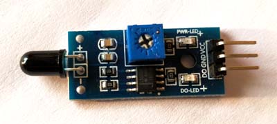
  • Fire or Flame sensors (3)

  • SG90 Servo Motor

  • L293D Motor Driver module

  • Mini DC Submersible Pump

  • Small Breadboard

  • Robot chassis with motors and wheels

  • Small can (for water container)

  • Connecting wires


How the Fire Fighting Robot Works


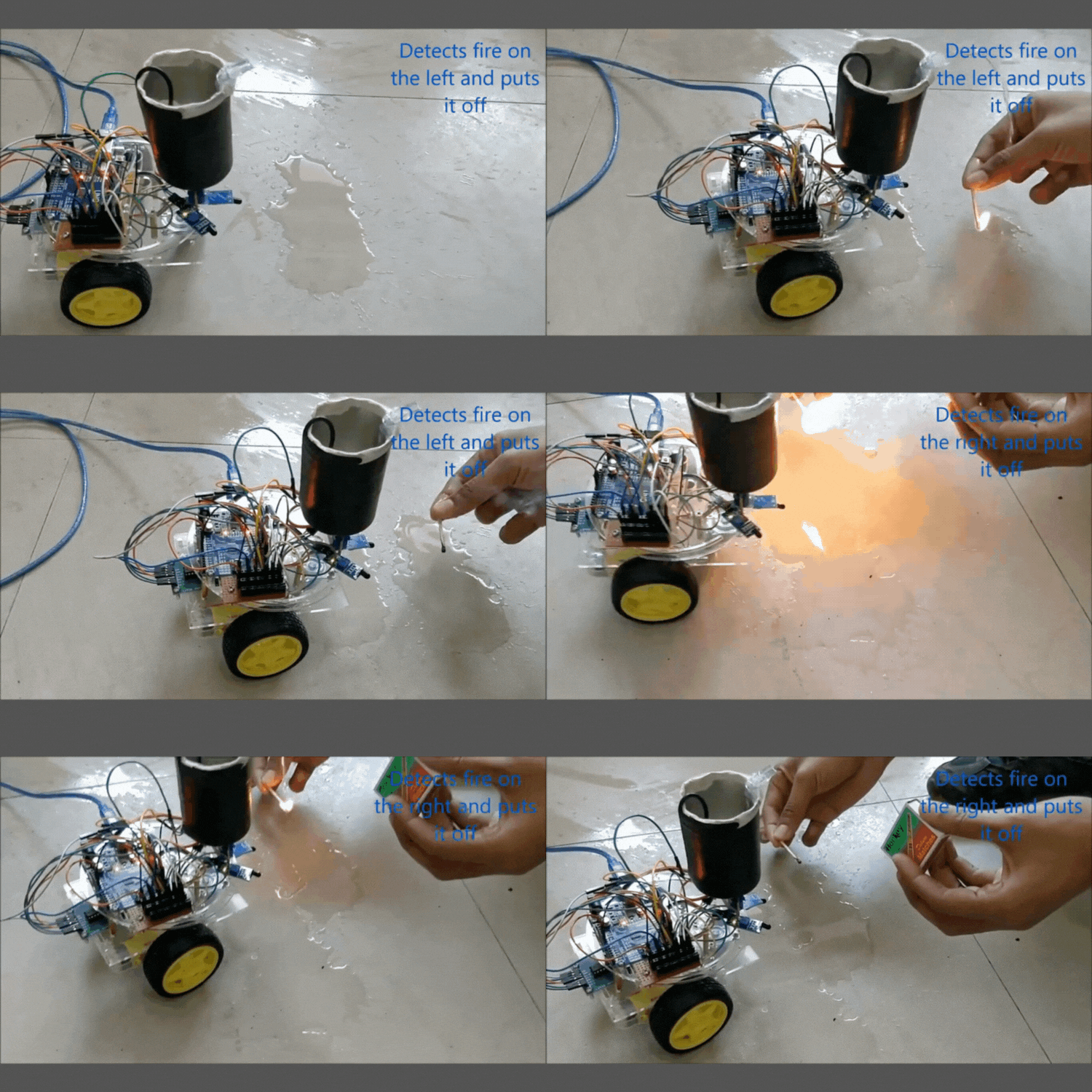
Our robot uses Arduino and flame sensors to detect fires. When it senses a fire, it calculates the fire's direction using sensor data and moves towards it with motor control. Once close to the fire, the robot activates a mini water pump mounted on a servo motor to spray water and extinguish the flames.


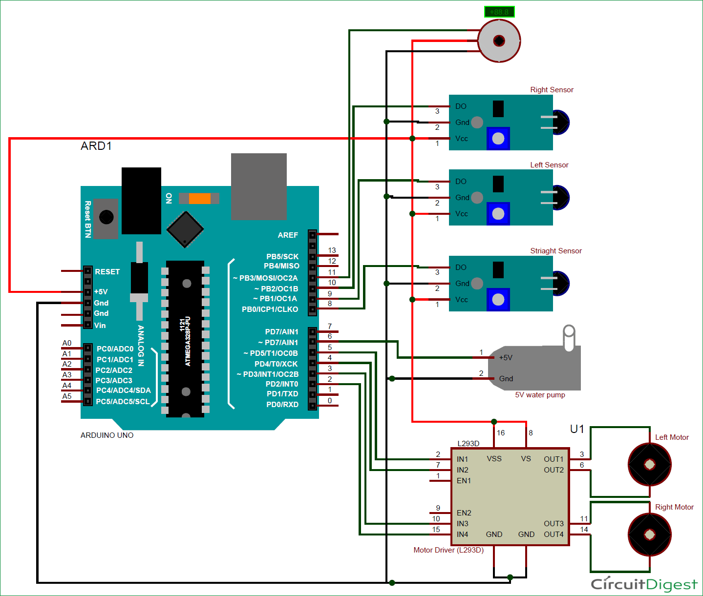
Follow the circuit diagram to assemble your Fire Fighting Robot. The connections are simple and can be adjusted based on your specific robot chassis and pump setup.


Use the provided Arduino code to control the robot's movements and water spraying. Customize the code to fine-tune the robot's behavior based on your preferences.


Testing and Deployment


Before putting your robot to work, test each component to ensure everything functions correctly. Once assembled, watch as your robot detects fires and springs into action to extinguish them with precision.


Conclusion


Building a Fire Fighting Robot with Arduino is not just a fun project—it's a meaningful introduction to the world of robotics. Let's use technology to improve safety and protect lives from the dangers of fire.


Explore more robotics projects and share your experiences in the comments or forums. 


Wednesday, 14 February 2024

Manual Techniques for Controlling Multiple Servos


The PCA9685 16-channel 12-bit PWM/Servo Driver module provides precise control over multiple PWM outputs, making it ideal for applications requiring accurate control over servos, LEDs, and various devices. This project aims to explore its functionalities, particularly focusing on how to control servo motors, to offer users a comprehensive understanding of its capabilities.

Required Components:

  • Arduino Uno R3
  • 8 * SG90 Servo Motors
  • PCA9685 16-Channel Module
  • External 5v Adapter
  • Jumper Wires

Interfacing Servo with Arduino:

Servo motors utilize PWM signals for precise control over their rotation angle. They typically feature three wires: VCC for power, GND for ground, and PWM for control signals. Connecting a servo to an Arduino involves supplying power and linking the PWM wire to a digital PWM pin. The Servo.h library enables servo control by uploading the Sweep Sketch to the Arduino IDE.

Arduino's limited number of PWM output pins poses challenges for scenarios requiring control over multiple servos. Complex techniques like multiplexing or software PWM may not offer accurate servo control. The PCA9685 module effectively addresses this limitation.

The PCA9685 module simplifies servo control by providing 16 free-running PWM outputs using only two pins, operated through I2C communication. It supports a wide range of applications, including robotics, automation, and lighting control. The module's features, such as a built-in clock and compatibility with 3.3V microcontrollers, enhance its versatility.

Programming the PCA9685 with Arduino:

Utilizing the Adafruit_PWMServoDriver library facilitates easy control of the PCA9685 module. By initializing the module and setting the PWM frequency, servo control becomes straightforward. The setPWM() function allows for precise control over servo angles, enabling smooth and synchronized motion. Prior to powering the setup, thorough checking of connections is crucial. Eight servos are connected to channels 0 to 7 of the PCA9685 module, powered by an external adapter for sufficient power. Monitoring angle and pulse data through the serial display provides insights into servo motion.

In summary, the PCA9685 16-Channel Servo Driver module offers a practical solution for precise control over multiple PWM outputs, particularly suited for applications involving servo motor control. Throughout this project, we've explored its functionalities, including interfacing methods and programming with Arduino.