Showing posts with label IoTApplications. Show all posts

Friday, 17 April 2026

ESP32-CAM WhatsApp Image Alert System – Capture & Send Photos Instantly

Send an Image Via WhatsApp Using ESP32-CAM

We use WhatsApp every day without even thinking about it. Sending messages, sharing photos, and staying connected has become second nature. But what if your electronics project could do the same - capture an image and send it directly to WhatsApp?

That’s exactly what this project Esp32 Cam whatsapp message does. Using an ESP32-CAM and CircuitDigest Cloud, you can build a simple system that captures an image and sends it to your phone instantly.

What This Project Does

This setup turns your ESP32-CAM into a smart alert system. With just a push button, the module captures an image and sends it to a WhatsApp number in real time.

No GSM module. No complex APIs. Just WiFi and a simple HTTPS request.

Press a button → capture image → send to WhatsApp

Simple as that.

How It Works

Circuit-Diagram-of-ESP32-based-image-Sent-in-Whatsapp

The working principle is straightforward and efficient.

A push button is connected to GPIO13. When you press it, the ESP32-CAM triggers the camera and captures an image using its onboard sensor and flash LED. The image is then processed and sent to CircuitDigest Cloud using a secure HTTP request.

The cloud platform handles everything else-formatting the message and delivering the image directly to WhatsApp.

Your microcontroller doesn’t deal with WhatsApp directly. It just sends the data, and the cloud does the heavy lifting.

Components You’ll Need

The hardware setup is minimal:

  • ESP32-CAM module
  • Push button
  • Breadboard
  • Jumper wires
  • 5V power supply

If your ESP32-CAM doesn’t have a USB interface, you’ll need a USB-to-Serial converter for programming.

Hardware Setup

The connections are clean and beginner friendly. The push button is wired to GPIO13 and ground, using an internal pull-up configuration in code. The onboard flash (GPIO4) is used to illuminate the scene during image capture.

Once powered, the system is ready to respond to a button press and trigger image capture instantly.

Behind the Code

The code is structured into simple logical blocks.

First, it connects to WiFi using your credentials. Then it initializes the camera with proper settings like resolution, JPEG format, and memory handling.

When the button is pressed, the system:

  • Captures an image
  • Stores it in memory
  • Turns on flash briefly for better clarity
  • Sends the image via HTTPS

The image is sent as multipart form data along with your API key and template ID. Once received, the cloud platform delivers it to your WhatsApp number.

What You’ll See

When everything is set up, pressing the button will instantly send a WhatsApp message with the captured image.

You’ll receive:

  • The image captured in real time
  • Event details (like trigger action)

It feels just like someone sent you a photo - except it came from your project.

Real-World Applications

This project isn’t just a demo - it’s actually useful.

You can use it for:

  • Home security alerts
  • Doorbell camera systems
  • Intrusion detection
  • Wildlife monitoring
  • Smart automation triggers

Anywhere you need instant visual feedback, this system fits perfectly.

Things to Keep in Mind

Stable power is important. The ESP32-CAM can be sensitive to voltage drops, so a reliable 5V supply is recommended.

Also, make sure your WiFi connection is strong enough for smooth image transmission.

This project is a great example of combining IoT with real-world communication tools. It takes something we use daily - WhatsApp - and integrates it with embedded systems in a practical way.

With just a few components and simple code, you can build a smart system that captures and shares moments automatically. It’s simple, powerful, and a lot of fun to build.

Friday, 20 March 2026

IoT-Based Smart Energy Meter Using ESP32 with MQTT and SMS Alerts

Keeping track of electricity usage is becoming more important than ever, especially with rising energy costs and the need for efficient power management. But what if you could monitor your home’s energy consumption in real time and get alerts instantly when something goes wrong?

That’s exactly what this ESP32 based Smart Energy Meter Using IoT does. It combines real-time monitoring with remote access and SMS alerts, making it a practical and powerful project for both beginners and advanced users.

What This Project Does

This smart energy meter uses the PZEM-004T sensor along with an ESP32 to measure key electrical parameters like voltage, current, power, energy consumption, frequency, and power factor.

The ESP32 then sends this data to an MQTT dashboard, allowing you to monitor everything remotely from your browser. At the same time, the system displays live values on an LCD for local viewing.

The most useful feature is the SMS alert system. If the system detects abnormal conditions such as high voltage or unusual current flow, it immediately sends an alert to your phone using a cloud API. This adds an extra layer of safety and awareness.

Why Use the PZEM-004T?

The PZEM-004T module makes this project much easier compared to traditional sensors. It comes factory-calibrated and can measure multiple parameters without complex setup.

It supports:

  • Voltage (80–260V AC)
  • Current (up to 100A using CT)
  • Power and energy consumption
  • Frequency and power factor

Since all calculations are handled internally, the ESP32 simply reads the data through UART communication, making the system more reliable and accurate.

How the System Works

The working of this project is simple but effective.

The PZEM-004T sensor measures electrical parameters from the AC supply. A current transformer (CT) is placed around the live wire to detect current safely without direct contact.

The ESP32 reads this data continuously and processes it. It then sends the data to an MQTT broker, which updates the dashboard in real time.

At the same time:

  • The LCD displays values like voltage and current
  • The Serial Monitor shows debugging data
  • The MQTT dashboard shows live remote data

If any parameter crosses a defined threshold (for example, high voltage), the ESP32 triggers an SMS alert through the cloud API.

Why MQTT Is Used

MQTT plays a key role in this project. Unlike traditional HTTP, MQTT is lightweight and designed for real-time communication.

It offers:

  • Low latency for instant updates
  • Minimal bandwidth usage
  • Continuous connection without repeated requests

This makes it perfect for streaming sensor data in real time.

SMS Alert Feature

One of the standout features of this project is its SMS alert system.

Whenever an abnormal condition is detected, the ESP32 sends a request to the cloud API. The cloud then sends an SMS to your registered phone number.

For example:

  • High voltage detected
  • Sudden drop in current
  • Unusual electrical behavior

A cooldown mechanism ensures that messages are not sent repeatedly, keeping notifications controlled and meaningful.

Applications

This smart energy meter can be used in many real-world scenarios.

It is useful for:

  • Monitoring household electricity usage
  • Detecting electrical faults early
  • Managing energy in remote locations
  • Building smart home automation systems

It can also be expanded further for predictive maintenance and energy optimization.

Conclusion

The IoT Smart Energy Meter using ESP32 is a practical and efficient solution for real-time energy monitoring. It combines accurate measurement, remote access, and instant alerts in a simple setup.

By using MQTT for fast data transmission and adding SMS alerts for safety, this project goes beyond basic monitoring and becomes a complete smart energy solution.

Whether you’re a student, hobbyist, or someone interested in smart systems, this project is a great way to understand how IoT can make everyday systems smarter and more reliable.

https://circuitdigest.com 

Robotics Projects |Arduino Projects | Raspberry Pi Projects|

Tuesday, 8 July 2025

Learn to Build Your Own Gas Leak Detector with Arduino – Simple DIY Safety Project

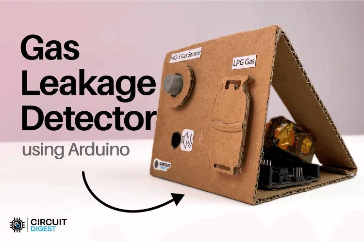
Ever thought about how devices can sniff out gas leaks and keep you safe, without you lifting a finger? That’s where a gas leakage detector comes in. It's a simple yet useful project you can build yourself using Arduino. In this guide, we will walk you through how to make your own gas detection system with all the schematics and code you need to get started.

What is a Gas Leakage Detector?

A gas leakage detector uses MQ-5 gas sensor to identify the presence of combustible gases such as LPG, methane, and smoke in the air. When gas concentration exceeds a certain threshold, it triggers a buzzer and alerts users through a connected display or indicator.

Components Required

To build this project, you will need:

  • Arduino Uno
  • MQ-5 Gas Sensor
  • Buzzer
  • LED
  • 16x2 LCD Display (with I2C Module)
  • Resistors
  • Jumper Wires & Breadboard
  • 5V Power Supply

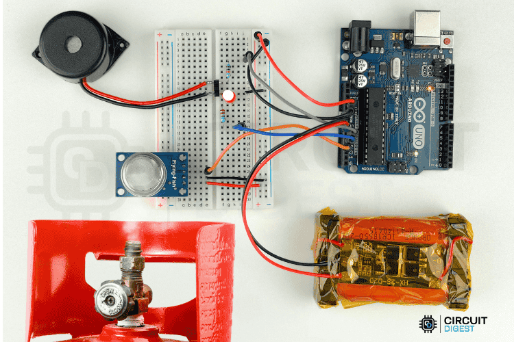
Gas Leakage Detector Using Arduino Project


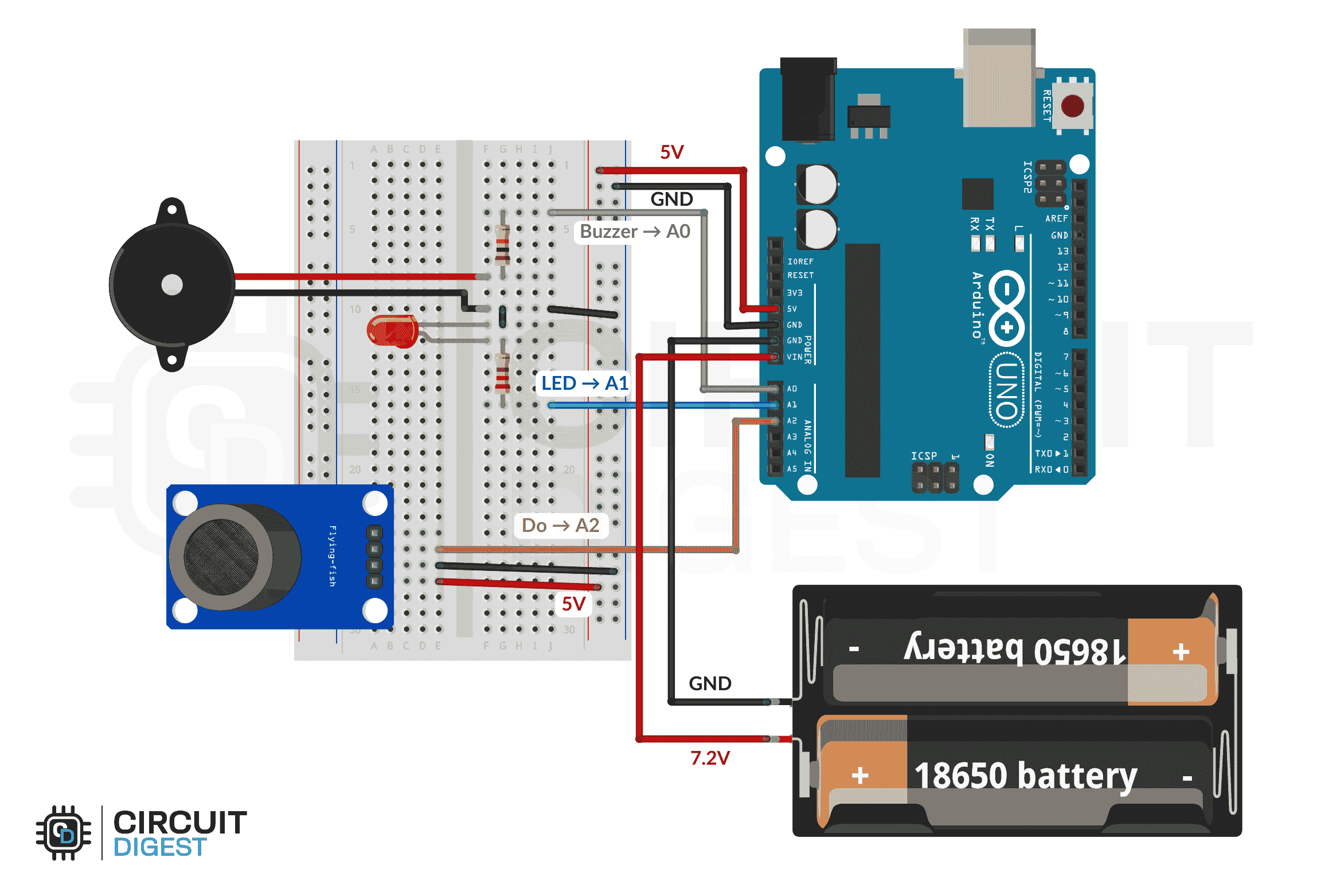
Circuit Diagram of Gas Leakage Detector Using Arduino

The MQ-5 sensor’s digital output goes to pin A2, while a buzzer (on A0) and an LED (on A1) provide alerts when gas is detected. A common ground is shared, and you can also power the system using USB or a regular adapter. When gas is detected, the Arduino turns on a buzzer and LED.

Circuit Diagram of Gas Leakage Detector Using Arduino

Applications of Gas Leakage Detectors

  • Home safety and kitchen monitoring
  • Industrial gas leak detection
  • Smart home automation systems
  • Educational electronics and IoT projects

Click here to explore the project in detail: How to Build a Gas Leakage Detector Using Arduino: Complete DIY Guide

https://circuitdigest.com 

Robotics Projects |Arduino Projects | Raspberry Pi Projects|

Thursday, 15 May 2025

ESP32 DIY Desktop Weather Station

DIY Desktop Weather Station
Want to keep an eye on the weather without constantly checking your phone? 
This DIY Desktop Weather Station has you covered! It features an ESP32-S3 board that connects to Wi-Fi and fetches real-time weather updates, like temperature, humidity, and current conditions, directly from the OpenWeatherMap API. For indoor readings, it includes a built-in HPP845E031R4 sensor that monitors your room's temperature and humidity. Its E-Ink display consumes very little power and can operate for days on a single charge. After each weather update, it automatically enters sleep mode to conserve even more energy.

Components Required

  • ESP32-S3-WROOM-1-N16R8
  • 4.2" EPD (E-Ink) Display
  • HPP845E031R4 Temperature & Humidity Sensor
  • ADP124ACPZ 3.3V LDO Regulator
  • MAX1898 Battery Charger IC

Desktop Weather Station Schematic Diagram

The weather station uses a custom-designed multi-color PCB that keeps the build neat, compact, and professional-looking. The PCB was designed using KiCad, and its dimensions are approximately 105mm × 90mm, making it perfect for desktop use. The design not only simplifies assembly but also adds a polished finish to the final product.
Desktop Weather Station Schematic Diagram

Assembling the Desktop Weather Station

Once the components are soldered and the board is assembled, simply power up the device and place it on your desk. The ESP32-S3 will handle all the background tasks, connecting to Wi-Fi, retrieving weather data, displaying it clearly on the E-Ink screen, and then entering sleep mode to save power.

Assembling the Desktop Weather Station PCB

It’s a compact, energy-efficient, and functional weather station that updates you with real-time information both indoors and outdoors. Whether you're building it for fun, education, or smart home integration, it’s a rewarding and practical DIY project.

The ESP32-S3-based Desktop Weather Station is a sleek and low-power solution for real-time weather updates. It combines wireless connectivity, local sensing, and an E-Ink display for a complete smart desktop gadget. With its clean PCB design and minimal component list, it’s perfect for electronics enthusiasts and makers. Whether for personal use or a tech-savvy gift, this project is both useful and fun to build.

For full assembly details and code:  How to Build a Desktop Weather Station Using ESP32 and E-ink Display


Friday, 17 May 2024

Design Tips and Troubleshooting Guide for MCP2200 Protocol Converter

 The MCP2200, developed by Microchip Technology, serves as a USB-to-UART serial converter, facilitating the conversion of USB connections to serial interfaces.


Design Considerations


  • Ensure proper connectivity and voltage levels between the MCP2200 and connected devices.

  • Strategic placement of the USB port close to the IC for efficient data transfer.

  • Direct routing of data lines and minimal use of vias to reduce signal interference.

  • Include filter capacitors and maintain tight component arrangement to optimize performance.


Troubleshooting Tips


  • Verify signal connections and check voltage compatibility to address communication failures.

  • Test functionality by matching serial settings with connected devices and performing a loopback test for data transmission.

  • Use alternative USB cables to rule out potential cable issues.


Microcontroller programming, debugging, industrial control systems, DIY electronics projects, legacy device support, automation, and robotics. Alternatives include CH340, MA112AS16, FT230x, CP2102, PL2303HX, CH9102, CH343, CH341, CP2110, and FT232.


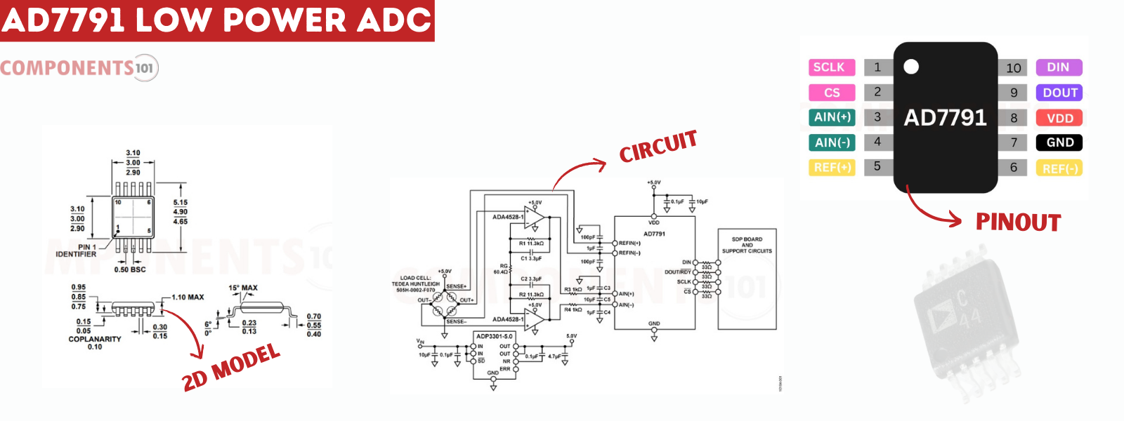
Detailed mechanical drawings and dimensions aid in creating custom footprints for PCB or CAD modeling, ensuring accurate integration of the MCP2200 into electronic designs. For detailed technical specifications and mechanical drawings, refer to the MCP2200 datasheet available here.


Tuesday, 16 April 2024

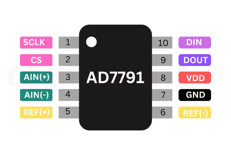
Troubleshooting and Design Tips for the AD7791 Low Power ADC


The AD7791 is a 24-bit sigma-delta analog-to-digital converter (ADC) developed by Analog Devices, known for its low-power and low-noise characteristics. It is widely employed in precision measurement applications due to its exceptional resolution and noise performance. Notably, the AD7791 incorporates an internal clock, eliminating the need for an external clock signal. Users can program the output data rate from 9.5Hz to 120Hz, offering flexibility in data acquisition speed.

Operating at a 3V supply, the AD7791 consumes a mere 225uW, making it suitable for battery-powered devices. It communicates with microcontrollers or digital systems via a serial interface and is available in a compact 10-pin MSOP package.


Key Features:


Input voltage range from -2.5V to 5.25V

Low current consumption: 75 μA (maximum)

RMS noise: 1.1 μV at 9.5 Hz update rate

Integral nonlinearity: 3.5 ppm typical

Simultaneous rejection of 50 Hz and 60 Hz noise

Internal clock oscillator

Rail-to-rail input buffer

VDD monitor channel

Temperature range: -40°C to +105°C


Troubleshooting Tips for AD7791:


  • Unstable Performance or Noise Issues: Ensure stable power supply and use bypass capacitors to prevent noise and disturbances.

  • No Signals from the IC: Verify correct power supply levels and check all connections, including SPI lines and analog inputs.

  • SPI Communication Problems: Confirm hardware connections and review programming details like bit order and clock phase for SPI communication.


Design tips for AD7791


How to minimize noise while using AD7791?

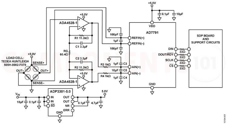
Use 10 µF tantalum capacitors in parallel with 0.1 µF capacitors to decouple VDD to GND. Place decoupling components as close as possible to the device for optimal performance. Decouple all logic chips with 0.1 µF ceramic capacitors to DGND.


Is the ADP7791 sensitive to ESD?

Yes. The performance and working of the IC are well affected by ESD.


How to order ADP7791?

You can check with your supplier with the following part numbers, AD7791BRM, AD7791BRMZ, AD7791BRM-REEL and AD7791BRMZ- REEL. These are all 10 MSOP packages, the only difference is how they are supplied and their markings.


What are the design considerations when designing a PCB using AD7791?


When designing a PCB for the AD7791, it's crucial to separate the analog and digital sections to prevent interference. Employ a minimum etch technique for ground planes to achieve effective shielding against noise. Connect the AD7791's GND pin to the AGND plane and carefully plan current paths to minimize signal disturbances. Keep digital and analog signals segregated to reduce potential noise and interference. Ensure power supply lines are wide to provide low impedance paths and minimize glitches. Shield fast-switching signals like clocks to prevent noise radiation. Avoid crossing digital and analog traces, and orient traces on opposite sides of the board at right angles to minimize feedthrough effects. While a microstrip technique is optimal, it may not be feasible for double-sided boards. In this approach, ground planes are on the component side, with signals on the solder side, optimizing signal integrity and minimizing noise.


The AD7791 is notable for its use in applications such as smart transmitters, battery-powered devices, portable instrumentation, sensor measurement, temperature and pressure measurement, weight scales, and 4 to 20 mA loops.


The device's performance can be optimized by following specific design considerations, such as proper decoupling, PCB layout considerations, and adherence to ESD protection measures. Additionally, designers can choose from various package options based on their project requirements, including AD7790 and AD7792, as alternatives within the same product family HX711, MCP3008, ADS1115, ADC0804, MCP3301.


For more details, refer to the AD7791 datasheet and technical resources.