Showing posts with label RTC. Show all posts

Friday, 20 March 2026

Learn Interfacing Raspberry Pi Pico RTC Module Step-by-Step

Interfacing Raspberry Pi Pico RTC DS3231

If you’ve ever built a digital clock using a microcontroller, you probably noticed one big problem — it loses time when power is removed. That’s exactly where a Real-Time Clock (RTC) module comes in.

In this project, we’re building a reliable digital clock using the Raspberry Pi Pico RTC DS3231 Module, along with a 16x2 I²C LCD to display time, date, and even temperature.

But this isn’t just a simple clock. It’s a solid foundation for future projects like alarms, schedulers, or automation systems.

Why Use the DS3231 RTC?

DS3231 Pinout

Not all RTC modules are equal. Older ones like the DS1307 tend to drift over time, especially with temperature changes. The DS3231 solves this problem with a built-in temperature-compensated crystal oscillator (TCXO).

What does that mean in simple terms?
It automatically adjusts itself based on temperature, so your clock stays accurate whether it’s hot or cold.

Another great feature is the backup battery support. Even if your Pico loses power, the RTC keeps running. So when power comes back, your time is still correct — no resetting needed.

What This Project Does

This setup uses:

  • Raspberry Pi Pico as the controller
  • DS3231 RTC module for accurate timekeeping
  • 16x2 I²C LCD for display

The system shows:

  • Current time
  • Date
  • Temperature (from the RTC module itself)

Since the LCD is small, the code smartly switches between different information instead of showing everything at once.

How It Works

DS3231 RTC Module Schematic

The entire system runs on I²C communication, which is one of the simplest ways to connect multiple devices.

Both the RTC module and LCD share the same two wires:

  • SDA (data)
  • SCL (clock)

The Pico reads time and temperature from the DS3231 and updates the LCD every second.

The best part?
Once you set the time initially, the RTC handles everything on its own.

Setting the Time (Important Step)

There are two easy ways to set the time:

  • Auto method (recommended):
    The RTC takes the current time from your computer during code upload.
  • Manual method:
    You can set a custom date and time directly in the code.

Just remember - after setting the time once, disable that line. Otherwise, it will reset every time the board restarts.

Real-World Uses

This project may look simple, but it’s actually very powerful.

You can use it for:

  • Alarm systems
  • Scheduled automation (like turning lights ON/OFF)
  • Data logging with timestamps
  • Timers and reminders

Once you understand this, you can build much bigger systems.

Common Issues (Quick Tips)

If something doesn’t work, check these first:

  • RTC not working → Battery might be missing or dead
  • LCD showing weird text → Wrong I²C address (try 0x27 or 0x3F)
  • No output → Check SDA and SCL connections

Most problems come down to wiring or small configuration mistakes.

This project is more than just a clock. It teaches you how to:

  • Work with I²C communication
  • Use RTC modules properly
  • Display real-time data on LCD

And once you’ve built this, you’ve got a strong base for more advanced projects.

Simple build. Practical use. And honestly — a great project to level up your embedded skills.

Interfacing Raspberry Pi Pico RTC DS3231 : Easy Setup Guide & Code

https://circuitdigest.com 

Robotics Projects |Arduino Projects | Raspberry Pi Projects|

Wednesday, 2 July 2025

RFID-Based Attendance System with Arduino


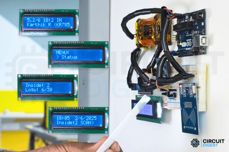
Keeping track of attendance should not feel like a daily hassle. Whether you are running a classroom, managing a small office, or organizing a community event, a simple, low-cost solution can go a long way. This RFID based attendance system using Arduino reads RFID cards to automatically log check-ins and check-outs, shows updates on an LCD, and stores attendance logs with real-time stamps using an RTC module. It's completely offline and stores data locally, so no need for an internet connection. The total cost is just around $30.

Why Choose Arduino for DIY RFID Attendance Tracker?

Arduino gives you full control over the system’s features without depending on expensive or limited commercial options. The MFRC522 RFID reader is accurate, and combining it with real-time clock and EEPROM modules means your data is both timestamped and safely stored, even during a power cut. Plus, once built, this setup is fully reusable and expandable for future upgrades like IoT integration or door control.

Key Features of RFID based attendance system

  • Automated RFID card scanning for both entry and exit
  • Real-time timestamp logging using DS1307 RTC
  • Local data storage with EEPROM, survives reboots
  • LCD display for live updates
  • Menu navigation via push buttons or serial monitor
  • Customizable card programming with personal data

Overview-Image-of-RFID-Based-Attendance-System-Using-Arduino

Components You’ll Need

  • Arduino Uno
  • MFRC522 RFID Reader
  • DS1307 RTC Module (with built-in AT24C32 EEPROM)
  • 16x2 I2C LCD Display
  • Push Buttons (x2)
  • RFID Cards/Tags
  • Breadboard, jumper wires, and 5V–12V power supply

RFID-Attendance-System-Using-Arduino
Real-World Applications

  • Classrooms – Track student attendance and prevent proxy entries
  • Offices – Log employee in/out times without manual input
  • Gyms & Clubs – Track member usage, ensure hygiene with contactless logging
  • Workshops – Monitor visitor entry or workshop sessions
  • Healthcare & Industry – Touchless logging for safety zones or shift tracking
This RFID based attendance system using Arduino is a great DIY project for anyone looking to solve a real problem while learning valuable electronics and programming skills. It’s affordable, fully offline, and scalable. Once set up, it can handle real-time check-ins, and you will know exactly how every part works.

Tuesday, 5 March 2019

Digital Wall Clock using Atmega16 and DS3231 RTC

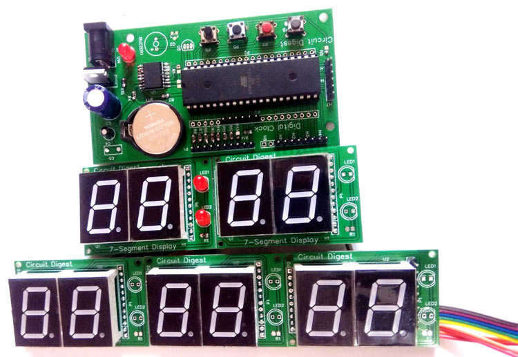
This is a DIY PCB project for a Digital wall clock, which is made using Atmega16 microcontroller and DS3231 RTC module.


In this Digital Clock Project, ten common anode 7-segment displays of 0.8-inch are used to display time and date. Here seven segment displays are used to show hour, minute, date, month and year. Our PCB design also has options to display seconds and temperature, which can be displayed by adding more display units.

You can watch the video below for more details of this AVR project.