Showing posts with label Arduino Project. Show all posts

Thursday, 7 May 2026

Automatic Waste Segregation System Using Arduino UNO Q

Automatic Waste Segregation System Using Arduino UNO Q

Waste segregation is important for recycling and environmental protection, but in daily life many people throw all waste into a single bin. To solve this problem, this project demonstrates an automatic waste segregation system using the Arduino UNO Q, Edge Impulse, and computer vision. The system can automatically identify different types of waste and sort them without manual effort.

This  Automatic Waste Segregation System project uses a USB camera and an AI-based object detection model to recognize waste materials such as:

  • Paper
  • Plastic
  • Cardboard
  • Battery

Once the object is detected, the system performs different actions using a servo motor and buzzer. Paper and cardboard are directed into the biodegradable section, plastic goes into the non-biodegradable section, and batteries trigger a buzzer alert because they are considered hazardous waste.

Why Arduino UNO Q?

The Arduino UNO Q is used as the main controller because it combines intelligent processing with reliable hardware control. Unlike traditional Arduino boards, it can handle both AI-based object detection and real-time hardware operations efficiently. This makes it ideal for smart automation projects like waste segregation.

Components Required

The project uses the following components:

  • Arduino UNO Q
  • USB Camera
  • Servo Motor
  • Buzzer
  • USB Hub
  • Jumper Wires
  • Cardboard Bin Structure
  • Laptop for programming
Components used in Smart Waste Segregation Project

Software Platforms Used

Edge Impulse

Edge Impulse is used to collect image data, label waste categories, and train the object detection model. The trained model is then optimized for embedded systems.

Arduino App Lab

Arduino App Lab is used to integrate the trained AI model with the hardware system. It manages communication between the Python application and the Arduino UNO Q.

How the System Works

Circuit  Diagram for Automatic Waste Segregation System

The USB camera continuously captures live video frames. The Edge Impulse object detection model analyzes each frame and identifies the waste type with a confidence score.

To avoid false detections, the system uses:

  • Confidence thresholds
  • Stability counters
  • Cooldown timers

When the same object is detected consistently, the system triggers the required action.

Waste Sorting Actions

Waste TypeAction
Paper/CardboardServo rotates to 0°
PlasticServo rotates to 180°
BatteryBuzzer activates

After sorting, the servo automatically returns to its default 90° position.

Python and Arduino Control

The project uses two interconnected programs:

Python Code

The Python application handles:

  • Camera input
  • Object detection
  • Stability checks
  • Sending commands to hardware

Arduino Code

The Arduino sketch controls:

  • Servo motor movement
  • Buzzer activation
  • Communication with the Python application

This combination enables smooth real-time waste detection and sorting.

Real-World Applications
Labelling Process of Different Items

This smart waste segregation system can be used in:

  • Homes
  • Schools and colleges
  • Offices
  • Shopping malls
  • Public waste collection systems
  • Smart city recycling solutions

It can also be used as an educational project for learning embedded AI, IoT, and automation.

Future Improvements

The system can be upgraded further by adding:

  • Detection for glass and metal waste
  • Mobile app monitoring
  • Solar-powered operation
  • Cloud-based waste analytics
  • LED indicators and voice feedback

These improvements can make the system more suitable for large-scale smart waste management applications.

This project presents a simple and practical automatic waste segregation system using Arduino UNO Q and Edge Impulse. By combining AI-based object detection with real-time hardware control, the system can automatically identify and sort waste materials efficiently.

The project demonstrates how embedded machine learning can be used to build low-cost smart recycling solutions that improve waste management and reduce environmental impact

https://circuitdigest.com 

Robotics Projects |Arduino Projects | Raspberry Pi Projects|

Saturday, 18 April 2026

AI-Based Hand Gesture Control Robot Using OpenCV

Gesture control is quickly becoming a natural way to interact with machines. Instead of relying on buttons or joysticks, this project lets you control a robot using simple hand movements. By combining computer vision with wireless communication, this system creates a responsive and intuitive control experience.

This Hand Gesture Control Robot Using OpenCV project demonstrates a hand gesture control robot using OpenCV, where a laptop webcam detects hand movements and translates them into motion commands for a rover.

How the System Works

At its core, the system follows a three-stage process: gesture detection, wireless transmission, and motor execution.

A Python program running on a laptop captures live video through a webcam. Using OpenCV and MediaPipe, it detects 21 key points on the hand and determines which fingers are raised. Based on this pattern, the system identifies gestures like forward, backward, left, right, or stop.

Once a gesture is recognized, the program sends a simple command (like “F” or “L”) via serial communication to an Arduino Nano acting as a transmitter. This Arduino then forwards the command wirelessly using the nRF24L01 module.

On the robot side, another Arduino Nano receives the command and controls the motors through an L298N Motor Driver, allowing the rover to move accordingly.

Key Components

Components-Used-In-Gesture-Controlled-Robot

The setup uses easily available components, making it accessible for students and hobbyists:

  • Two Arduino Nano boards
  • Two nRF24L01 wireless modules
  • L298N motor driver
  • 4-wheel DC motor chassis
  • Laptop with webcam
  • 12V battery pack

Each component plays a specific role, from gesture processing to wireless communication and motor control.

Gesture Recognition with OpenCV

The vision system is powered by OpenCV and MediaPipe. OpenCV handles camera input and frame processing, while MediaPipe detects hand landmarks in real time.

The system identifies finger positions and converts them into commands:

  • Index finger → Forward
  • Two fingers → Backward
  • Thumb + index → Left
  • Three fingers → Right
  • Open hand or fist → Stop

This logic keeps the system simple while ensuring accurate gesture detection.

Wireless Communication

Gesture-Controlled-Robot-Transmitter

The nRF24L01 modules enable low-latency wireless communication between the controller and the robot. Commands are transmitted as single characters, keeping the data lightweight and fast.

With proper configuration, the system achieves reliable communication within a short range, making the robot feel responsive and smooth during operation.

Robot Movement and Control

On receiving a command, the rover executes it instantly. The L298N motor driver controls the direction and speed of the motors using PWM signals.

For safety and stability, the system limits motor speed to around 50%, ensuring controlled movement without overloading the hardware.

Real-World Applications

This project goes beyond just a demo and opens doors to practical applications:

  • Contactless robotic control systems
  • Assistive technology for accessibility
  • Surveillance and remote-controlled vehicles
  • Educational platforms for robotics and AI
  • Human-machine interaction research

This hand gesture control robot combines computer vision, wireless communication, and embedded systems into a single project. It offers a hands-on way to understand how modern interfaces work and how machines can respond to natural human input.

With its simple design and powerful concept, this project is a great starting point for building advanced gesture-controlled systems and exploring real-time robotics.

https://circuitdigest.com 

Robotics Projects |Arduino Projects | Raspberry Pi Projects|


Saturday, 28 March 2026

Arduino Send Email Notifications Using DHT11 and UNO R4 WiFi

Temperature Monitoring System and Email Alerts Using Arduino

Keeping track of temperature and humidity sounds simple… until you actually need to monitor it constantly. Whether it’s your room, a server setup, or even a greenhouse, conditions can change quickly without you noticing. That’s where automation really helps.

In this project, we build a simple Arduino Send Email Notifications system that keeps you updated in real time. Using an Arduino UNO R4 WiFi and a DHT11 sensor, the system continuously monitors environmental conditions and sends an email alert whenever the temperature crosses a set limit.

What This Project Does

At its core, this is a smart monitoring system. The DHT11 sensor keeps reading temperature and humidity, while the Arduino checks if the values stay within a safe range.

The moment the temperature exceeds a predefined threshold, the system automatically sends an email notification using a cloud API. No need to manually check anything - you get notified instantly.

It’s simple, practical, and surprisingly useful in real-world scenarios.

Components Required

Hardware Setup of Arduino Based Alert System

The best part about this project is how minimal the hardware is. You only need:

  • Arduino UNO R4 WiFi
  • DHT11
  • Breadboard
  • Jumper wires

That’s it. No GSM module, no extra hardware - WiFi does all the work here.

How the Setup Works

Temperature Alert System with Email Notification Using Arduino

The wiring is straightforward. The DHT11 sensor connects to the Arduino with just three main connections:

  • VCC - 5V
  • GND - GND
  • Data - Digital Pin 2

Once powered, the Arduino connects to your WiFi network using its built-in wireless capability. This is what allows it to communicate with the cloud and send email alerts.

How the System Works

Here’s what happens behind the scenes:

  • The sensor continuously reads temperature and humidity
  • Arduino compares the temperature with a preset threshold
  • If everything is normal - no action
  • If temperature crosses the limit - alert triggered

At that moment, the Arduino creates a JSON request and sends it securely to the CircuitDigest Cloud Email API. The cloud service then formats the message and delivers it straight to your inbox.

To avoid spamming, the system includes a smart control mechanism. Once an email is sent, it won’t send another until the temperature returns to normal and crosses the threshold again.

Code Logic in Simple Terms

The program is divided into a few clear steps:

  • Connect to WiFi
  • Read sensor data
  • Check temperature condition
  • Send email if needed

It uses secure HTTPS communication, ensuring your data is safely transmitted to the cloud server before the email is generated.

Where You Can Use This

This project is more than just a demo. It has real-world applications:

  • Server room monitoring
  • Home temperature alerts
  • Cold storage systems
  • Industrial safety monitoring
  • Greenhouse automation

Basically, anywhere temperature matters - this system fits right in.

This Send Email Notifications using Arduino system is a perfect example of how a simple sensor project can become much more powerful with IoT integration. Instead of just displaying values on a screen, it actively notifies you when something goes wrong.

It’s beginner-friendly, practical, and easy to expand. You can later add features like SMS alerts, dashboards, or even multiple sensors.

If you're stepping into IoT projects, this is a great place to start - simple build, real-world value, and a solid learning experience.

https://circuitdigest.com 

Robotics Projects |Arduino Projects | Raspberry Pi Projects|

Thursday, 26 March 2026

DIY Arduino Handheld Game Console Using UNO R4 WiFi

Handheld Arduino Game Console

Tired of building the same old Arduino projects like blinking LEDs and basic sensors? Then it’s time to try something more exciting. This DIY handheld Arduino game console transforms your development skills into a fun, interactive experience where you can actually play games on hardware you built yourself.

This compact console is powered by the Arduino UNO R4 WiFi and features a small OLED display, tactile buttons, and a buzzer for sound effects. Despite its simple design, it packs multiple retro-style games, making it perfect for beginners and hobbyists who want to explore both hardware and software in a creative way.About

About This Arduino Game Console

This project is a portable Arduino game console. It includes a 0.96-inch OLED display, four control buttons, and a buzzer, all mounted on a custom HAT-style board. The console runs 10 classic-style games like Snake, Pong, and Tetris, each written separately in modular code files.

Console Highlights

Working of DIY-Handheld-Arduino-Game-Console

The console is designed to be compact and fully portable. Powered by a LiPo battery with a boost converter, it can be used anywhere without external power. The OLED display provides smooth graphics, while the buttons offer simple and responsive controls.

The games included are optimized for the hardware, giving a nostalgic retro gaming feel without heavy processing requirements.

Components Required

DIY-Handheld-Arduino-Game-Console-Hardware-Setup

To build this console, you only need a few essential components: Arduino UNO R4 WiFi, OLED display, push buttons, buzzer, LiPo battery, and a boost converter. These parts are assembled on a perfboard to create a compact and clean design.

Building the Console

All components are mounted on a perfboard designed like a HAT that sits directly on top of the Arduino. This approach keeps the design neat and portable compared to messy breadboard wiring.

Careful wiring and compact placement ensure stability and better usability during gameplay.

Code Structure

The software is written in a modular way where each game is stored in a separate header file. This makes it easy to add or modify games without affecting the entire system.

The main program handles menu navigation, input reading, and launching games based on user selection.

Challenges & Fixes

During development, two main challenges were faced. First, compatibility issues with display libraries were solved by switching to the U8g2 library. Second, button bouncing caused unwanted inputs, which was fixed using software debouncing logic.

Conclusion

This Arduino game console project is a great way to combine creativity with electronics. It goes beyond basic circuits and gives you a real, usable device that you can play with.

Whether you're a beginner or an experienced maker, this project helps you understand embedded systems, display handling, and user interaction in a fun and practical way.

https://circuitdigest.com 

Robotics Projects |Arduino Projects | Raspberry Pi Projects|

Thursday, 18 December 2025

Dual Axis Solar Tracker Using Arduino


Dual Axis Solar Tracker

As the demand for clean and sustainable energy grows, improving how efficiently we harvest solar power has become just as important as generating it. While solar panels are widely used today, many of them remain stationary and miss out on a significant portion of available sunlight as the sun moves across the sky. This limitation makes solar tracking systems an effective solution for maximizing energy capture throughout the day.

This Dual Axis Solar Tracker using Arduino solves that problem by automatically adjusting the solar panel’s position in both horizontal and vertical directions, ensuring maximum sunlight exposure from sunrise to sunset.

Overview of the Dual Axis Solar Tracker System

A dual axis solar tracker is an automated system that aligns solar panel with the sun’s position using two axes of movement: azimuth (left–right) and elevation (up–down). In this project, an Arduino UNO processes light data from four LDR sensors and controls two servo motors to keep the panel facing the brightest light source.

Compared to fixed or single-axis systems, this approach can improve energy output by up to 30–40%, making it ideal for efficient solar harvesting.

Components Used

Hardware

  • Arduino UNO
  • 4 × LDR sensors
  • 2 × Micro servo motors
  • Solar panel
  • 10kΩ resistors
  • Breadboard and jumper wires

Software

  • Arduino IDE

Dual-Axis-Solar-Tracker-Circuit-Diagram


How the System Works

The four LDR sensors are placed in a cross arrangement to detect light intensity from all directions. The Arduino continuously compares light levels between left–right and top–bottom sensor pairs.

  • If one side receives more light, the corresponding servo motor rotates the panel toward that direction.
  • When sunlight is weak or during nighttime, the system enters standby mode to prevent unnecessary movement.

This real-time feedback loop allows the panel to stay optimally aligned with the sun throughout the day.

Advantages of a Dual Axis Solar Tracker

  • Higher energy generation than fixed panels
  • Automatic daily and seasonal adjustment
  • Better morning and evening performance
  • Low-cost implementation using Arduino
  • Ideal for educational and renewable energy projects

The Arduino-based Dual Axis Solar Tracker using LDR and servo motors is a practical and efficient solution for maximizing solar energy output. By intelligently tracking the sun in both directions, the system significantly improves panel efficiency while using affordable components and simple control logic. This project is an excellent example of how smart electronics and renewable energy can work together for a sustainable future.

Wednesday, 21 May 2025

DIY Smart Helmet with Alcohol, Drowsiness and Theft Detection Using Arduino Uno

Road accidents are a major global concern, especially involving two-wheeler riders. Many of these accidents are due to drunk driving, drowsiness, or not wearing a helmet. The IoT Based Smart Helmet aims to reduce these risks by integrating safety features directly into the helmet. This project incorporates alcohol detection, drowsiness detection, helmet wear detection, and theft detection to ensure the rider’s safety and enforce responsible riding behavior.

Working Principle

The system is designed to prevent the bike from starting unless all safety conditions are satisfied:
  • IR sensor detects if the helmet is worn.
  • MQ-3 sensor checks for alcohol in breath.
  • If alcohol is detected, buzzer sounds and vehicle stays off.
  • Drowsiness detection monitors rider’s alertness.
  • RF transmitter sends data from helmet to vehicle.
  • Vehicle starts only if all safety conditions are met.
Parts Marking of Smart Helmet Transmitter Side

Transmitter Side

  • Arduino UNO R3 
  • 433 MHz RF Transmitter 
  • IR Sensor - wear detection and drowsiness detection
  • MQ-3 Sensor - alcohol detection
  • LED & Buzzer
  • Helmet 
  • Breadboard 
Receiver Side
  • Arduino UNO R3
  • 433 MHz RF Receiver
  • 16x2 LCD Display with I2C Module
  • 1-Channel Relay Module
  • LED & Buzzer
  • Breadboard
Sleep Detection By Smart Safety Helmet

Applications
  • Two-Wheeler Safety
  • Smart Transportation
  • Theft Prevention
  • Educational Tool
For full assembly details and code Smart Helmet using Arduino

Wednesday, 23 April 2025

DIY Smart Blind Stick Using Arduino Nano

Smart Blind Stick using Arduino and Ultrasonic sensor

Navigating daily environments can be difficult for visually impaired individuals. To improve mobility and safety, this project introduces a DIY smart blind stick using Arduino Nano, an ultrasonic sensor, and a buzzer. It’s simple, budget-friendly, and serves as a practical aid for obstacle detection. The system works by detecting nearby objects and alerting the user via sound and light signals.

How the Blind Stick Works

This Arduino-based stick functions as an assistive tool by constantly checking for nearby obstacles and triggering alerts. It includes:

  • Ultrasonic Sensor (HC-SR04): Detects objects by sending ultrasonic waves and receiving the reflected signal.
  • Arduino Nano: Acts as the central controller, calculating distance and triggering alerts.
  • Buzzer and LED: Provide audio and visual warnings depending on the proximity of obstacles.
Audio Based Obstacle Detection and Alerts Using Arduino


Obstacle Detection

The ultrasonic sensor emits a sound wave when triggered by the Arduino. When the wave hits an object, it reflects back and is received by the sensor’s echo pin. The time taken for the round trip helps calculate the distance.

Distance Calculation

The Arduino uses the following formula to calculate distance:

Distance = (Time taken by the signal to Hit and bounce back / 2) / 29.1

For example, a 500µs round-trip means the object is roughly 8.59 cm away.

Alerts

If the object is within 50 cm:

  • Buzzer: Emits a beep. The closer the object, the faster the beep.
  • LED: Flashes similarly, helping those with partial vision.

Components Required

  • Arduino Nano
  • HC-SR04 Ultrasonic Sensor
  • 5V Buzzer
  • LED
  • 220Ω Resistor
  • 9V Battery
  • On/Off Switch
  • Breadboard and Wires
  • PVC Pipe for stick body

Block Diagram

The block diagram includes the Arduino Nano at the center, connected to the ultrasonic sensor (for input) and buzzer/LED (for output). A 9V battery powers the system.

Block Diagram Representation of Arduino-Based Blind Stick

Circuit Diagram

The sensor’s VCC, TRIG, ECHO, and GND are connected to Arduino pins. The buzzer and LED are connected to output pins through resistors. The entire circuit is powered by the battery via a switch.

Note: The sensor draws around 15mA, which is safe to power directly from Arduino GPIO pins.

Hardware Assembly

All components are placed on a small breadboard and fixed to a PVC pipe using zip ties. The battery is mounted with double-sided tape. The sensor is positioned at the top to detect obstacles ahead.

Hardware Connections of Obstacle Detection Stick for the Blind

Arduino Code Overview

The code reads distance and triggers alerts based on it. It uses millis() for multitasking of the buzzer and LED.

Uploading Code

  1. Open Arduino IDE.
  2. Select the board: Arduino Nano (ATmega328P).
  3. Choose the correct COM port.
  4. Paste and upload the code.

Once uploaded, your Arduino Nano starts working as the control unit for the blind stick.

Final Assembly

Fix the entire circuit onto the PVC pipe. Position the ultrasonic sensor to face forward and secure components using zip ties or tape. Ensure the switch is easily accessible for quick power control.

Assembling Blind Stick Circuit on a PVC Pipe

This project is a basic yet functional solution to help people with vision challenges navigate safely. It uses minimal components, is easy to assemble, and can be enhanced further with features like GPS or vibration alerts. You can find the full code and diagrams on the GitHub repository in the original tutorial.

Wednesday, 5 March 2025

How to Build an RFID Door Lock System Using Arduino


Learn how to build an  RFID-based door lock system using an Arduino Uno, an RFID module, and a servo motor. The system scans an RFID card, checks its ID, and unlocks the door if it’s authorized. This setup is useful for home security, office access control, and smart automation projects.

Components Required

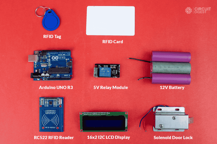
  • Arduino Uno (or compatible board)
  • RC522 RFID Module (to read RFID tags)
  • RFID Cards & Key Fobs (for authentication)
  • Servo Motor (to control the lock)
  • Buzzer & LED Indicators (for access feedback)
  • Jumper Wires & Breadboard (for connections)


Components Required to make RFID Door Lock System Using Arduino
Components Required to make RFID Door Lock System Using Arduino

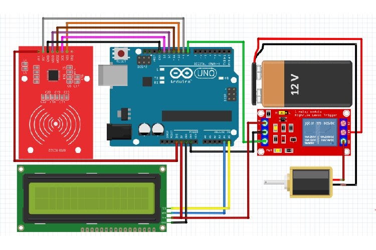
RFID Door Lock System using Arduino Circuit Diagram


Circuit Diagram RFID Door Lock System using Arduino
Circuit Diagram RFID Door Lock System using Arduino

The RFID door lock system works by scanning an RFID card or key fob using the RC522 RFID module. When a card is scanned, the Arduino reads its unique ID and checks if it matches a pre-stored authorized ID. If the card is recognized, the servo motor unlocks the door, allowing access. If the card is not authorized, the system triggers a buzzer and an LED indicator to signal access denial. After a short delay, the lock resets and waits for the next scan, ensuring continuous operation.

Arduino Code to Read RFID Card UID

To find your authorized RFID card UID, compile and upload the code to your Arduino. No hardware modifications are needed.

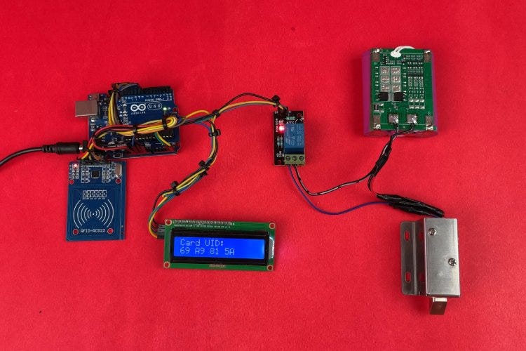
Complete Hardware Setup of RFID Door Lock System using Arduino
Complete Hardware Setup of RFID Door Lock System using Arduino

Code for RFID Door Lock System using Arduino

This Arduino-based RFID door lock system reads an RFID card’s UID, checks it against a predefined UID, and unlocks the door for 10 seconds using a relay and solenoid lock while displaying the status on an LCD.

Step-by-Step Guide

Step 1: Setting Up the Hardware

Start by assembling the required components. Connect the RC522 RFID module to the Arduino Uno using SPI communication. Attach the relay module and solenoid lock for door control, and connect the LCD display to show access status. Ensure the power supply is stable for reliable operation.

Step 2: Uploading the UID Retrieval Code

To get the unique ID (UID) of your RFID card, compile and upload the UID retrieval code to the Arduino. This step doesn’t require any hardware modifications. Once uploaded, open the Serial Monitor in the Arduino IDE to view the scanned UID.

Step 3: Storing the Authorized UID

After retrieving the UID, update the main code by replacing the default UID with your card’s UID. This ensures that only the authorized card can unlock the door. Save and re-upload the modified code to the Arduino.

Step 4: Implementing the Door Lock System

The main program continuously scans for RFID cards. When a card is detected, the Arduino checks if its UID matches the stored UID. If authorized, the relay activates the solenoid lock, unlocking the door for 10 seconds. Meanwhile, the LCD display updates the door status.

Step 5: Testing and Final Adjustments

Test the system by scanning different RFID cards. If unauthorized, the lock remains closed, and the system displays an access denied message. Adjust the servo angles, delay timings, or security features as needed for better performance.


Final Testing of our RFID Door Lock System
Working Demo video : 

Enhancements & Customization

  • Store multiple RFID card IDs for multi-user access.
  • Add an OLED display to show authentication messages.
  • Integrate Wi-Fi or Bluetooth for remote access control.
  • Connect to a database for logging entry records.

This RFID-based door lock system offers a simple yet effective way to manage access control. It can be expanded with additional features to enhance security and functionality. 


Learn more about this tutorial  How to make an RFID Door Lock System using Arduino?

Get the more projects with full code and schematics on our https://circuitdigest.com 

Robotics Projects |Arduino Projects | Raspberry Pi Projects|