Monday, 4 February 2019

Interfacing ESP8266 with ARM7-LPC2148 and Creating a Webserver to control an LED


ESP8266 Wi-Fi transceiver provides a way to connect a microcontroller to the network. It is widely used in IoT projects as it is cheap, tiny and easy to use. This WiFi module can be used with any microcontroller to connect it with internet. In some of the following tutorials, it is used with Arduino and Raspberry pi, to create webserver such as Raspberry webserver and Arduino webserver.
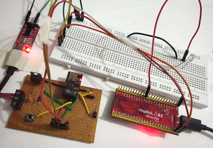
ESP8266 Interfacing with ARM7-LPC2148- Creating a Webserver to control an LED

To interface an ESP8266 Module with the ARM7-LPC2148 microcontroller and create a webserver to control the LED connected to LPC2148. The workflow will go like this:

  • Send AT commands from LPC2148 to ESP8266 to configure ESP8266 in AP mode
  • Connect the laptop or computer Wi-Fi with the ESP8266 Access point
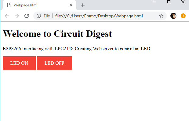
  • Create a HTML webpage in PC with Access point IP address of the ESP8266 webserver
  • Create a program for LPC2148 to control the LED according to the value received from ESP8266


If you are completely new to ESP8266 Wi-Fi module visit the below links to get familiar with ESP8266 Wi-Fi module.


You can check the complete tutorial to interface ESP8266 module with LPC2148:  https://circuitdigest.com/microcontroller-projects/iot-based-ARM7-LPC2148-webserver-to-control-an-led 

Wednesday, 23 January 2019

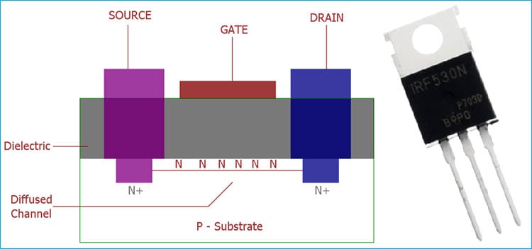
What is MOSFET and Where are they Used?

MOSFET is basically a transistor which uses field effect. MOSFET stands for Metal Oxide Field Effect Transistor, which has a gate. The gate voltage determines the conductivity of the device. Depending on this gate voltage we can change the conductivity and thus we can use it as a switch or as an amplifier like we use Transistor as a switch or as an amplifier.

MOSFET Amplifier

MOSFET provides very high input impedance and it is very easy to bias. So, for a linear small amplifier, MOSFET is an excellent choice. The linear amplification occurs when we bias the MOSFET in the saturation region which is a centrally fixed Q point.

Check out the following article to learn more about MOSFETs

Monday, 10 December 2018

Interfacing OLED Display with Android Phone

connecting OLED display with Android Phone using bluetooth

Most of us would be familiar with the 16×2 Dot matrix LCD display that is used in many projects to display some information to the user. But these LCD displays have a lot of limitation in what they can do. In this tutorial, we will use OLED to display some basic information from the Android smartphone like Time, date, network strength and battery status. This project provides a basic idea and framework to build an Arduino based SmartWatch and can be further extended to display incoming calls, messages and many more on OLED display.

Here you can find the basic circuit diagram to interface the OLED with Android phone using a bluetooth module:

Circuit Diagram for Interfacing OLED display with Android Phone to build a Smart Watch

To check out the complete project with codes and required libraries for arduino, visit the link below:

Thursday, 29 November 2018

Basics of Stepper Motor

From a simple DVD player or printer in your home to a highly sophisticated CNC machine or Robotic Arm, Stepper motors are to be found almost everywhere. Its ability to make electronically controlled precise movements have made these motors find application in many felids like surveillance cameras, Hard disk, CNC machines, 3D Printers, Robotics, Assembly robots, Laser cutters and much more.
28BYJ-48 Stepper Motor
Image Source: Components101

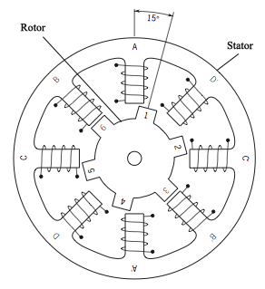
Like all motors the stepper motors also have a stator and a rotor, but unlike a normal DC motor the stator consists of individual sets of coils. The number of coils will differ based on type of stepper motor, but for now just understand that in a stepper motor the rotor consists of metal poles and each pole will be attracted by a set of coil in the stator. The below diagram shows a stepper motor with 8 stator poles and 6 rotor poles.


If you take a look at the coils on the stator, they are arranged in terms of coil pairs, like A and A’ forms a pair B and B’ forms a pair and so on. So each of this coil pair’s form an electromagnet and they can be energised individually using a driver circuitry. When a coil gets energised it acts as a magnet and the rotor pole gets aligned to it, when the rotor rotates to adjust itself to align with the stator it is called as one step. Similarly by energising the coils in a sequence we can rotate the motor in small steps to make a complete rotation.

Source and read more: Stepper motor tutorial

Wednesday, 17 October 2018

Audio Amplifier Circuit Design Tutorials

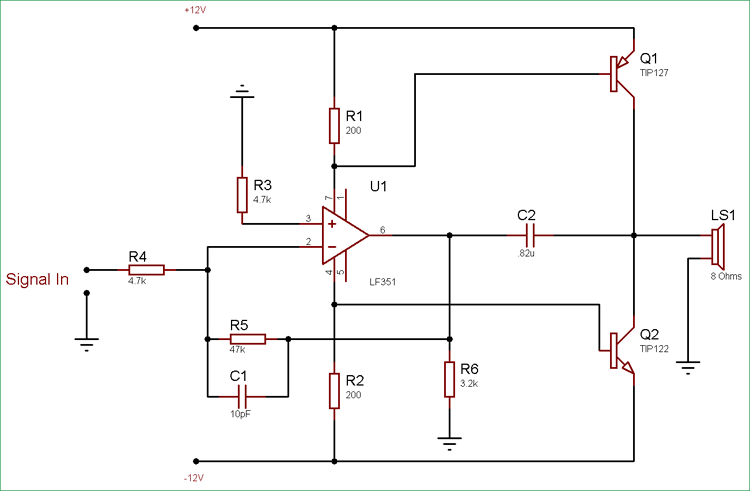
Amplifiers are the backbone of Analog electronics. They are used vastly in the field of electronics industry. Amplifiers are used almost in all the audio related applications.  Power amplifier are designed to maximize the magnitude of the power of given input signal. In audio electronics, the operational amplifier increases the voltage of the signal, but unable to provide the current, which is required to drive a load.

10 Watt Audio Amplifier Circuit using Op-Amp and Power Transistors

Here I am sharing few tutorials to design audio amplifier circuits which delivers output in various ranges. Please click the links below and go through the tutorials which covers each amplifier in detail.


  • 10W Audio Amplifier using Op-Amp 
  • 25W Audio Amplifier Circuit
  • 40W Audio Amplifier using TDA2040 
  • 50W Amplifier Circuit using MOSFETs
  • 100W Audio Amplifier using MOSFET 


  • Hope you liked the tutorials!

    Wednesday, 19 September 2018

    Getting Started with STM32 Microcontroller

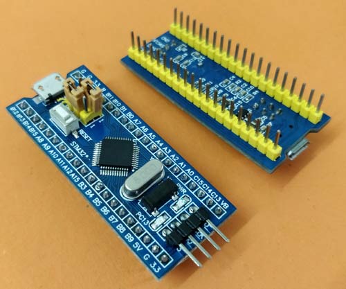
    Arduino would have been the first board for many hobbyists (including me) and engineers out there when they started with electronics. However, as we start building more and dig deep we would soon realise that Arduino is not industry ready and its 8-bit CPU with a ridiculously slow clock, it does not give you enough juice for your projects. Hopefully though, we have the new STM32F103C8T6 STM32 Development Boards (Blue Pill) in the market now which can easily outperform Arduino with its 32-bit CPU and ARM Cortex M3 architecture. Another honey pot here is that we can use the same old Arduino IDE to program our STM32 Boards. So in this tutorial, let us get started with the STM32 to know a bit of basics about this board and blink the on-board LED using the Arduino IDE. 


    The STM32 board a.k.a Blue Pill is a Development board for the ARM Cortex M3 Microcontroller. It looks very much similar to the Arduino Nano but it packs in quite a punch. The Development board is shown below.


    Working with STM32 development board is quite easy. You can check below the series of tutorials which covers basics as well as higher level tutorials in order of increasing difficulty.

    You can explore more STM32 tutorials and projects here: https://circuitdigest.com/stm32-projects-and-tutorials

    Tuesday, 28 August 2018

    Build An Arduino Based Self Balancing Robot!

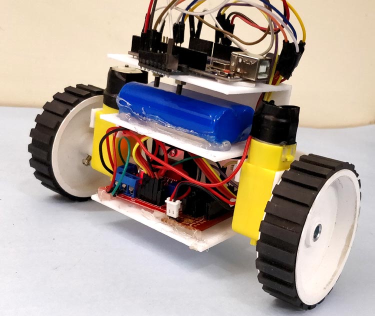
    After being inspired by RYNO motors and other self balancing scooters from Segway, I always wanted to build something similar. Thinking for while, I decided to build a Self Balancing Robot using Arduino. This way I would be able to grasp the underlying concept behind all these scooters and also learn how PID algorithm works.

    DIY Self Balancing Robot using Arduino

    When I started building this self balancing robot, I realized that this bot is a bit of a challenge to build. There are so many options to select from and hence the confusions start right form selecting the motors and remains till tuning PID values. And there are so many things to consider like type of battery, position of battery, wheel grip, type of motor driver, maintaining the CoG (Centre of gravity) and much more. But let me break it to you, once you build it you will agree that it’s not as hard as it sounds to be. So let’s face it, in this tutorial I will document my experience in building the self balancing robot. You might be an absolute beginner who is just getting started or might have landed up here after a long frustration of not getting your bot to work. This place aims to be your final destination.

    Below is the video of the Self Balancing Robot working.


    You can find the complete DIY instructions along with schematic diagram and codes, required to build this Self Balancing Robot in the following link: https://circuitdigest.com/microcontroller-projects/arduino-based-self-balancing-robot