How the Blind Stick Works
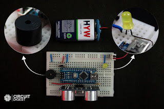
This Arduino-based stick functions as an assistive tool by constantly checking for nearby obstacles and triggering alerts. It includes:
- Ultrasonic Sensor (HC-SR04): Detects objects by sending ultrasonic waves and receiving the reflected signal.
- Arduino Nano: Acts as the central controller, calculating distance and triggering alerts.
- Buzzer and LED: Provide audio and visual warnings depending on the proximity of obstacles.
The ultrasonic sensor emits a sound wave when triggered by the Arduino. When the wave hits an object, it reflects back and is received by the sensor’s echo pin. The time taken for the round trip helps calculate the distance.
The Arduino uses the following formula to calculate distance:
For example, a 500µs round-trip means the object is roughly 8.59 cm away.
If the object is within 50 cm:
- Buzzer: Emits a beep. The closer the object, the faster the beep.
- LED: Flashes similarly, helping those with partial vision.
Components Required
- Arduino Nano
- HC-SR04 Ultrasonic Sensor
- 5V Buzzer
- LED
- 220Ω Resistor
- 9V Battery
- On/Off Switch
- Breadboard and Wires
- PVC Pipe for stick body
Block Diagram
The block diagram includes the Arduino Nano at the center, connected to the ultrasonic sensor (for input) and buzzer/LED (for output). A 9V battery powers the system.
Circuit Diagram
The sensor’s VCC, TRIG, ECHO, and GND are connected to Arduino pins. The buzzer and LED are connected to output pins through resistors. The entire circuit is powered by the battery via a switch.
Note: The sensor draws around 15mA, which is safe to power directly from Arduino GPIO pins.
Hardware Assembly
All components are placed on a small breadboard and fixed to a PVC pipe using zip ties. The battery is mounted with double-sided tape. The sensor is positioned at the top to detect obstacles ahead.
Arduino Code Overview
The code reads distance and triggers alerts based on it. It uses millis() for multitasking of the buzzer and LED.
- Open Arduino IDE.
- Select the board: Arduino Nano (ATmega328P).
- Choose the correct COM port.
- Paste and upload the code.
Once uploaded, your Arduino Nano starts working as the control unit for the blind stick.
Final Assembly
Fix the entire circuit onto the PVC pipe. Position the ultrasonic sensor to face forward and secure components using zip ties or tape. Ensure the switch is easily accessible for quick power control.
This project is a basic yet functional solution to help people with vision challenges navigate safely. It uses minimal components, is easy to assemble, and can be enhanced further with features like GPS or vibration alerts. You can find the full code and diagrams on the GitHub repository in the original tutorial.


.jpg)


No comments:
Post a Comment