Thursday, 24 April 2025

Types of Current Transformers: A Comprehensive Guide

Types of Transformers

Current transformers (CTs) are important in modern electrical systems, allowing safe measurement and protection in high-current setups like power plants and substations. They convert high AC currents into lower, manageable values for monitoring.

What is a Current Transformer?

A current transformer is a step-down transformer that converts high current in its primary winding to a smaller, proportional current in its secondary winding. This makes it possible to safely monitor high-voltage circuits using instruments like ammeters, relays, and energy meters.

  • Primary Winding: Connected in series with the high-current line.
  • Secondary Winding: Connected to meters or protective relays.
  • Isolation: Both windings are electrically isolated and wrapped around a magnetic core.
Current Transformer Working and Symbol

Types of Current Transformers Based on Applications

  • Metering Current Transformers

These are used for accurate measurement of electrical consumption. Commonly found in residential and industrial metering systems, they are small in size and made from high-grade laminated silica steel. They ensure safe and precise current measurements for billing and monitoring purposes.

  • Protection Current Transformers

Designed to protect electrical systems during fault conditions, these CTs are connected to protective relays that trip the circuit during overcurrent or short-circuit scenarios. They have larger cores made of cold-rolled silicon steel to handle high fault currents (up to 10–20 times the rated value) without saturation.

Current Transformers Based on Applications

Types of Current Transformers Based on Construction

Current transformers can also be classified based on their construction, which affects how they are installed and used in different electrical setups. The main types include bar-type, cable-type, bushing-type, and block-type CTs, each suited for specific environments and current ranges.

Types of Current Transformers Based on Phases

  • Single-Phase CTs

These transformers handle single-phase power systems and are widely used in residential and commercial power distribution. They are straightforward in design and easy to maintain.

  • Three-Phase CTs

These contain three cores (or a three-phase core) and offer simultaneous current measurement across all three phases. They're commonly used in industries, power plants, and energy management systems.

Current Transformer Types Based on Phases

Types of Current Transformers Based on Core Types

Current transformers can also be categorized based on the type of magnetic core used, which directly influences their performance, accuracy, and suitability for different applications. The main core types include wound core, toroidal (ring) core, and split core CTs.

Current transformers come in various forms to serve different roles in electrical systems, from measuring to protection, from compact indoor setups to large-scale industrial environments. Choosing the right type of CT depends on the application, system voltage, and space constraints.

For more in-depth details: Types of Current Transformers

Wednesday, 23 April 2025

DIY Smart Blind Stick Using Arduino Nano

Smart Blind Stick using Arduino and Ultrasonic sensor

Navigating daily environments can be difficult for visually impaired individuals. To improve mobility and safety, this project introduces a DIY smart blind stick using Arduino Nano, an ultrasonic sensor, and a buzzer. It’s simple, budget-friendly, and serves as a practical aid for obstacle detection. The system works by detecting nearby objects and alerting the user via sound and light signals.

How the Blind Stick Works

This Arduino-based stick functions as an assistive tool by constantly checking for nearby obstacles and triggering alerts. It includes:

  • Ultrasonic Sensor (HC-SR04): Detects objects by sending ultrasonic waves and receiving the reflected signal.
  • Arduino Nano: Acts as the central controller, calculating distance and triggering alerts.
  • Buzzer and LED: Provide audio and visual warnings depending on the proximity of obstacles.
Audio Based Obstacle Detection and Alerts Using Arduino


Obstacle Detection

The ultrasonic sensor emits a sound wave when triggered by the Arduino. When the wave hits an object, it reflects back and is received by the sensor’s echo pin. The time taken for the round trip helps calculate the distance.

Distance Calculation

The Arduino uses the following formula to calculate distance:

Distance = (Time taken by the signal to Hit and bounce back / 2) / 29.1

For example, a 500µs round-trip means the object is roughly 8.59 cm away.

Alerts

If the object is within 50 cm:

  • Buzzer: Emits a beep. The closer the object, the faster the beep.
  • LED: Flashes similarly, helping those with partial vision.

Components Required

  • Arduino Nano
  • HC-SR04 Ultrasonic Sensor
  • 5V Buzzer
  • LED
  • 220Ω Resistor
  • 9V Battery
  • On/Off Switch
  • Breadboard and Wires
  • PVC Pipe for stick body

Block Diagram

The block diagram includes the Arduino Nano at the center, connected to the ultrasonic sensor (for input) and buzzer/LED (for output). A 9V battery powers the system.

Block Diagram Representation of Arduino-Based Blind Stick

Circuit Diagram

The sensor’s VCC, TRIG, ECHO, and GND are connected to Arduino pins. The buzzer and LED are connected to output pins through resistors. The entire circuit is powered by the battery via a switch.

Note: The sensor draws around 15mA, which is safe to power directly from Arduino GPIO pins.

Hardware Assembly

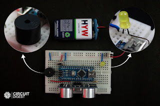
All components are placed on a small breadboard and fixed to a PVC pipe using zip ties. The battery is mounted with double-sided tape. The sensor is positioned at the top to detect obstacles ahead.

Hardware Connections of Obstacle Detection Stick for the Blind

Arduino Code Overview

The code reads distance and triggers alerts based on it. It uses millis() for multitasking of the buzzer and LED.

Uploading Code

  1. Open Arduino IDE.
  2. Select the board: Arduino Nano (ATmega328P).
  3. Choose the correct COM port.
  4. Paste and upload the code.

Once uploaded, your Arduino Nano starts working as the control unit for the blind stick.

Final Assembly

Fix the entire circuit onto the PVC pipe. Position the ultrasonic sensor to face forward and secure components using zip ties or tape. Ensure the switch is easily accessible for quick power control.

Assembling Blind Stick Circuit on a PVC Pipe

This project is a basic yet functional solution to help people with vision challenges navigate safely. It uses minimal components, is easy to assemble, and can be enhanced further with features like GPS or vibration alerts. You can find the full code and diagrams on the GitHub repository in the original tutorial.


Monday, 14 April 2025

Build GPS Tracker Using ESP32 and Visualize Data on Map


Simple GPS Tracker Using ESP32

This project shows how to create a GPS tracker using an ESP32 and NEO-6M GPS module. The tracker reads your current location and displays it on GeoLinker API, its a free API at Circuit Digest Cloud. It is a good starting point if you're interested in IoT or location-based tracking systems.

What is GPS Tracker

A GPS tracker is a device that uses satellite signals to determine the real-time location of a person, vehicle, or object. It is commonly used in navigation, safety, and tracking systems, and can be easily integrated into IoT projects using modules like the NEO-6M and ESP32.

How This Device Works

This project uses an ESP32 and NEO-6M GPS module to create a simple GPS tracker. The ESP32 sends location data to the GeoLinker API via HTTP, where it is plotted on a live map. It also stores data offline when there is no internet and syncs it once the connection is restored.
Working of GPS Tracker Using ESP32 and GeoLinker

ESP32 GPS Tracker Circuit Diagram

ESP32 GPS Tracker Circuit Diagram

Components Needed

You’ll need the following parts:

  • ESP32 development board
  • NEO-6M GPS module
  • Jumper wires
  • Breadboard
  • USB cable
  • Wi-Fi connection (for viewing maps)

Components Needed for making Simple GPS Tracker Using ESP32 and GeoLinker


Applications of GPS Trackers

  • Vehicle tracking
  • Pet and child tracking 
  • Fitness devices 
  • Asset tracking 
  • Navigation systems 

This simple GPS tracker project gives you a clear understanding of how to collect and display location data using the ESP32 and GPS module. It is a practical, entry-level project for anyone exploring IoT or GPS-based applications.

For full code, circuit diagram, and detailed instructions see the tutorial: Simple GPS Tracker with ESP32