Wednesday, 19 September 2018

Getting Started with STM32 Microcontroller

Arduino would have been the first board for many hobbyists (including me) and engineers out there when they started with electronics. However, as we start building more and dig deep we would soon realise that Arduino is not industry ready and its 8-bit CPU with a ridiculously slow clock, it does not give you enough juice for your projects. Hopefully though, we have the new STM32F103C8T6 STM32 Development Boards (Blue Pill) in the market now which can easily outperform Arduino with its 32-bit CPU and ARM Cortex M3 architecture. Another honey pot here is that we can use the same old Arduino IDE to program our STM32 Boards. So in this tutorial, let us get started with the STM32 to know a bit of basics about this board and blink the on-board LED using the Arduino IDE. 


The STM32 board a.k.a Blue Pill is a Development board for the ARM Cortex M3 Microcontroller. It looks very much similar to the Arduino Nano but it packs in quite a punch. The Development board is shown below.
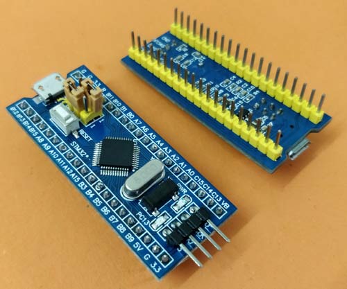

Working with STM32 development board is quite easy. You can check below the series of tutorials which covers basics as well as higher level tutorials in order of increasing difficulty.

You can explore more STM32 tutorials and projects here: https://circuitdigest.com/stm32-projects-and-tutorials

Tuesday, 28 August 2018

Build An Arduino Based Self Balancing Robot!

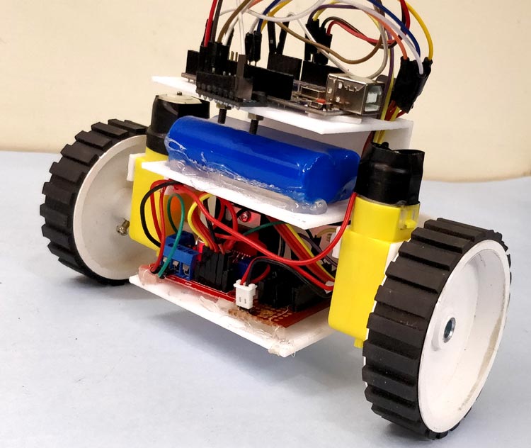
After being inspired by RYNO motors and other self balancing scooters from Segway, I always wanted to build something similar. Thinking for while, I decided to build a Self Balancing Robot using Arduino. This way I would be able to grasp the underlying concept behind all these scooters and also learn how PID algorithm works.

DIY Self Balancing Robot using Arduino

When I started building this self balancing robot, I realized that this bot is a bit of a challenge to build. There are so many options to select from and hence the confusions start right form selecting the motors and remains till tuning PID values. And there are so many things to consider like type of battery, position of battery, wheel grip, type of motor driver, maintaining the CoG (Centre of gravity) and much more. But let me break it to you, once you build it you will agree that it’s not as hard as it sounds to be. So let’s face it, in this tutorial I will document my experience in building the self balancing robot. You might be an absolute beginner who is just getting started or might have landed up here after a long frustration of not getting your bot to work. This place aims to be your final destination.

Below is the video of the Self Balancing Robot working.


You can find the complete DIY instructions along with schematic diagram and codes, required to build this Self Balancing Robot in the following link: https://circuitdigest.com/microcontroller-projects/arduino-based-self-balancing-robot

Friday, 1 June 2018

PIC Microcontroller Communication Tutorials

In the vast system of embedded applications, no microcontroller can perform all the activities by itself and so it has to communicate to other devices to share information. There are many different types of communication protocols used by microcontrollers to share these information’s, but the most used ones are USART, IIC, SPI and CAN. Each communication protocol has its own advantage and disadvantage. To learn how to work with these communication protocols in PIC microcontroller, Below are few tutorials which provide the complete guide to use these communication protocols.

1. PIC Microcontroller I2C Communication
I2C Communication with PIC Microcontroller PIC16F877

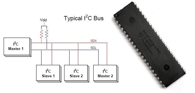
The term IIC stands for “Inter Integrated Circuits”. It is normally denoted as I2C or I squared C or even as 2-wire interface protocol (TWI) at some places but it all means the same. I2C is a synchronous communication protocol meaning, both the devices that are sharing the information must share a common clock signal. It has only two wires to share information out of which one is used for the cock signal and the other is used for sending and receiving data.
Click the link to learn more about PIC microcontroller I2C communication

2. PIC Microcontroller SPI communication
PIC16F877A PIC Microcontroller SPI Communication Tutorial

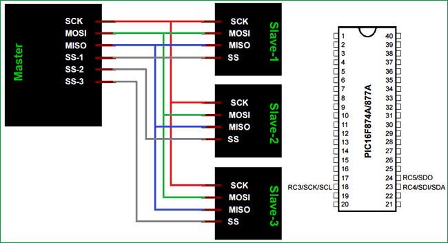
The term SPI stands for “Serial Peripheral Interface”. It is a common communication protocol that is used to send data between two microcontrollers or to read/write data from a sensor to a microcontroller. It is also used to communicate with SD cards, shift registers, Display controllers and much more. Know more about PIC SPI communication

3. PIC Microcontroller UART Communication
UART Communication using PIC Microcontroller

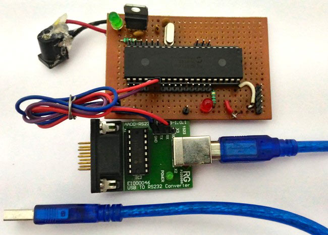
Here we have used PIC16F877A MCU, it has a module called “Addressable Universal Synchronous Asynchronous Receiver and Transmitter” shortly known as USART. USART is a two wire communication system in which the data flow serially. USART is also a full-duplex communication, means you can send and receive data at the same time which can be used to communicate with peripheral devices, such as CRT terminals and personal computers. Know more about PIC UART communication.

4. CAN Communication with PIC Microcontroller
Bring communication and connectivity in your embedded design to the next level with Microchip's Controller Area Network (CAN) bus solutions technology. Originally created for automotive applications, the CAN bus protocol is a high-speed, reliable communication protocol for applications requiring robust communications at bit rates reaching 8 Mbps. Incorporating the CAN bus protocol into your design is a low-cost, reliable way to function in a difficult electrical environment with a high degree of real-time capability. Learn more about CAN communication here.

Friday, 27 April 2018

5 Arduino Projects to Try for Intermediate DIYers

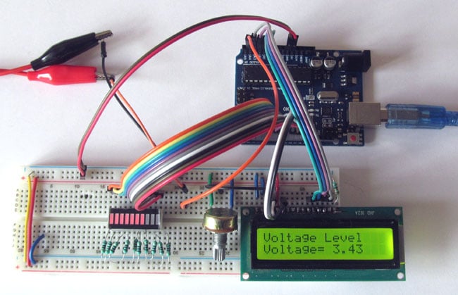
1. Battery Voltage Level Indicator on LED Bargraph

Battery Voltage Indicator using Arduino and LED Bar Graph
This Arduino battery voltage indicator indicates the status of the battery by glowing LEDs on a 10 Segment LED Bar Graph according to the battery voltage. It also shows your battery voltage on the LCD connected to the Arduino.

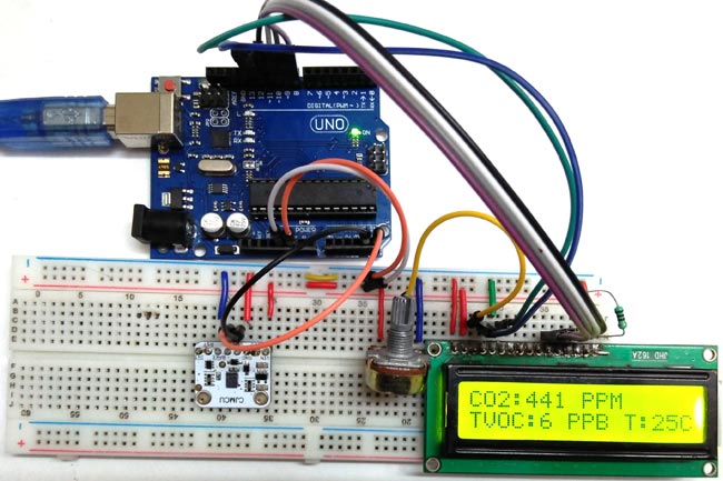
2. TVOC and CO2 Measurement using CCS811

TVOC and CO2 Measurement using Arduino and CCS811 Air Quality Sensor
For designing an air quality monitoring system we need durable and reliable air quality sensor. Although there are many Air Quality parameters but the most important are CO2 and TVOC. So for sensing CO2 and TVOC, we are using CCS811 Air Quality Sensor.


3. Automatic Pet Feeder Project

Automatic Pet Feeder using Arduino
This Arduino based Automatic Pet Feeder which can automatically serve food to your pet timely. It has a DS3231 RTC (Real Time Clock) Module, which used to set time and date on which your pet should be given food. So, by setting up the time according to your pet’s eating schedule, the device drop or fill the food bowl automatically.

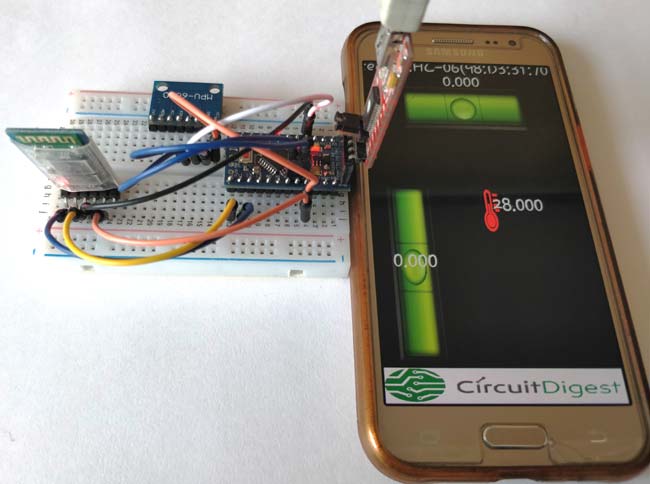
4. DIY Inclinometer

DIY Arduino Inclinometer using MPU6050
The MPU6050 is an IC 3-axis accelerometer and a 3-axis gyroscope combined into one unit. It also houses a temperature sensor and a DCM to perform a complex task. The MPU6050 is commonly used in building Drone and other remote robots like a self-balancing robot. In this project we will learn how to use the MPU6050 is built an Inclinometer or Spirit Leveller. As we know an inclinometer is used to check if a surface is perfectly leveled or not, they are available either as sprit bubble ones or as digital meters. In this project, we are going to build a Digital Inclinometer which can be monitored using an Android application. The reason for using a remote display like a mobile phone is that we can monitor the values from MPU6050 without having to look at the hardware, this would come very handy when the MPU6050 is placed on a drone or some other inaccessible locations.

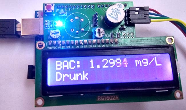
5. Alcohol Detector using Arduino

Arduino Alcohol Detector Circuit
This Arduino Alcohol Detectorwill detect the alcohol level in breath and by using some calculations in code we can calculate the alcohol level in breath or blood and can trigger some alarm. 

Wednesday, 27 December 2017

Learn All about Diodes


In general all the electronic devices need DC power supply but it is impossible to generate DC power so, we need an alternative to get some DC power thus the usage of diodes comes into the picture to convert AC power to DC power. A diode is a tiny electronic component used in almost all the electronic circuits to enable the flow of current in only one direction. We can say that the usage of semiconductor materials to build the electronic components was started with diodes. Before the invention of diode there were with vacuum tubes, where the applications of both these devices are similar but the size occupied by the vacuum tube will be much greater than the diodes. The construction of vacuum tubes is a bit complex and they are difficult to maintain when compared with the semiconductor diodes. Few applications of diodes are rectification, amplification, electronic switch, conversion of electrical energy into light energy and light energy into electrical energy.

Different types of Diodes

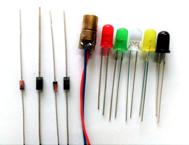
Picture Showing Different types of diodes.

Learn what is diode, PN-junction theory, construction and working of different types of diodes.

Thursday, 30 November 2017

Calculators for Electrical and Electronics Engineers & DIY Makers

These electrical and electronics engineering calculators are one of the most commonly used calculators by electronics students and circuit designers. These calculators solve common equations and formulas which takes quite a time so these calculators come handy by solving these calculations quickly.

Below is the list of calculators:

RMS Voltage Calculator
LED Resistor Calculator
Resistor Color Code Calculator
Op Amp Gain Calculator
LM317 Resistor/Voltage Calculator
Resistors in Parallel Calculator
Resistors in Series Calculator
Capacitor Value Calculator
555 Timer Astable Circuit Calculator
555 Timer Monostable Calculator
Voltage Divider Calculator
Ohm's Law Calculator

Tuesday, 28 November 2017

Raspberry Pi Based Ball Tracking Robot Project

Image recognition is one of the popular way in which the robots are thought to understand objects by looking at the real world through a camera just like we do. In this project we are going to use popular development board Raspberry Pi to build a Robot that could track ball and follow it just like the football playing robots do.

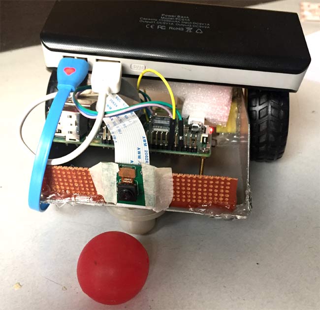
Below is the picture of the robot built here:

Raspberry Pi Ball Tracking Robot using processing

OpenCV is popular and open source tool for Image processing but in this DIY project we are using the Processing IDE to keep the project simple and easy to build.

Go to the link below to find the complete DIY project with required circuit connections and codes:
Ball Tracking Robot