Saturday, 31 May 2025

Understanding Flip-Flops in Digital Electronics

Flip Flop in Digital Electronics

Flip-flops are basic building blocks in digital electronics that work as simple 1-bit memory devices. In electronics Flip-Flop is "A bistable device with synchronous inputs that changes state only at specified transitions of a clock signal" (IEEE Standard 91/1984)". Unlike regular logic gates that respond instantly to inputs, flip-flops can store a value, either 0 or 1, and keep it until something changes it, usually through an input signal and a clock pulse. 

Because of this ability to hold information, they’re used in many sequential circuits like counters, registers, and parts of memory in microprocessors. The following tutorial will give you a complete understanding of Flip-Flops in Digital Electronics.

Difference Between Latch and Flip-Flop

A latch is level-triggered, meaning its output changes as long as the input is active. A flip-flop is edge-triggered, updating its output only on a specific clock edge (rising or falling).

Transistors → Logic Gates → Latches → Flip-Flops

Types of Flip Flops in Digital Electronics

  • SR Flip-Flop: This is the simplest type of flip-flop that uses Set (S) and Reset (R) inputs to store a bit. It’s great for basic memory storage, but it gets a bit tricky when both inputs are active at the same time.

SR flip-flop diagram


  • D Flip-Flop: Captures the value present at its D input when a clock pulse occurs, and this value is maintained as the output until the next clock pulse. This characteristic makes the D flip-flop a fundamental building block in registers, shift registers, and various other memory devices. 

d flip-flop circuit diagram


  • JK Flip-FlopThink of it as an improved version of the SR flip-flop that avoids the “invalid” state issue. It can toggle, set, or reset based on its J and K inputs and is very versatile in counters.

jk flip-flop circuit diagram


  • T Flip-Flop: Toggles the output on each clock cycle when T is high. It is particularly useful in applications like counters and control circuits.

t flip flop circuit diagram

Applications of Flip-Flops

  • Registers
  • Counters
  • Finite State Machines (FSMs)
  • Pipeline stages

Understanding flip-flops is crucial for anyone interested in digital electronics, as they form the basis for more complex sequential circuits and systems.

For a more detailed explanation and practical demonstrations, refer to the full article on Circuit Digest.: Flip-Flop in Digital Electronics: Types, Truth Table, Logic Circuit and Practical Demonstration


Tuesday, 27 May 2025

Build a Gesture-Controlled Drone Using ESP32 and MPU6050


Ever thought of flying a drone with just your hand gestures? In DIY Gesture Control Drone, we’ll walk you through building a gesture-controlled LiteWing drone using ESP32 and MPU6050. It’s affordable, beginner-friendly, and works using Python and Bluetooth. Whether you're a hobbyist or student, you’ll find the step-by-step tutorial easy to follow and fun to build

Hand Gesture Control esp32 mpu6050

Components Required for Drone Gesture Control Project

  • LiteWing Drone with battery 
  • VLX5311x ToF Sensor For height hold 
  • ESP32 dev module and mpu6050 for gesture control 
  • A computer with python installed
Features of Gesture Control Drone DIY Project 
  • Gesture Control
  • Wireless Communication
  • Stable Flying
  • Compact and Lightweight
Gesture CFLib python Litewing


How Gesture Control Works?
Gesture control refers to using, hand movements to operate devices without  physical contact. An MPU6050 sensor detects the tilt and motion of your hand, which is processed by an ESP32 microcontroller. These movements are then sent via Bluetooth, allowing you to fly the drone without a traditional remote. you can get full dettails on our tutorial on ESP32 Air Mouse.

For the complete tutorial, schematics and python code : DIY Gesture Control Drone using Python with LiteWing and ESP32

Thursday, 22 May 2025

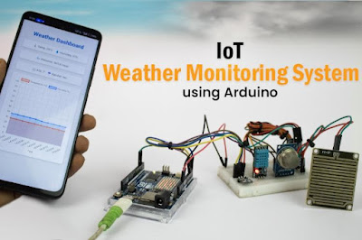
Weather Monitoring System Using Arduino UNO R4 WiFi

Weather Monitoring System

Learn how to create a simple IoT-based weather monitoring system using the Arduino UNO R4 WiFi. This project collects real-time data, such as temperature, humidity, air quality, rainfall, and atmospheric pressure, and displays the information on a local web dashboard. No cloud service or third-party platform is required, making this setup ideal for offline environments.

Features of the IoT Weather Monitoring System

  • Monitors temperature, humidity, air quality, pressure, and rainfall
  • Displays real-time readings on a local Wi-Fi dashboard
  • Operates without cloud connectivity
  • Built with Arduino UNO R4 WiFi, which includes onboard Wi-Fi
  • Easy to assemble and customize using basic electronic components

Components Required

Components required to build an Arduino Weather Monitoring System


To build this system, you'll need the following:

  • Arduino UNO R4 WiFi
  • DHT11 – Temperature and Humidity Sensor
  • BMP180 – Pressure Sensor
  • MQ135 – Air Quality Sensor
  • Rain Sensor Module
  • Breadboard and Jumper Wires
  • USB Cable for Programming

Circuit Diagram and Assembly of IoT based Weather Station System

Circuit Diagram for Arduino-Based Weather Monitoring System

How It Works

Once powered on, each sensor reads environmental data. The Arduino UNO R4 WiFi processes this data and hosts a local web page that displays real-time values. Since the dashboard is served over your local network, there's no dependency on internet access or cloud platforms. Any device connected to the same Wi-Fi can access it.

Real-World Applications

This weather station can be adapted for various use cases:

  • Educational Projects – Great for learning about sensors, IoT, and data visualization
  • Smart Homes – Monitor indoor/outdoor conditions for automation
  • Gardening & Agriculture – Track weather changes for irrigation or crop planning
  • Offline Setups – Works in remote areas without relying on cloud platforms

For Arduino code and full tutorial: How to Build an IoT-Based Weather Monitoring System Using Arduino

Wednesday, 21 May 2025

DIY Smart Helmet with Alcohol, Drowsiness and Theft Detection Using Arduino Uno

Road accidents are a major global concern, especially involving two-wheeler riders. Many of these accidents are due to drunk driving, drowsiness, or not wearing a helmet. The IoT Based Smart Helmet aims to reduce these risks by integrating safety features directly into the helmet. This project incorporates alcohol detection, drowsiness detection, helmet wear detection, and theft detection to ensure the rider’s safety and enforce responsible riding behavior.

Working Principle

The system is designed to prevent the bike from starting unless all safety conditions are satisfied:
  • IR sensor detects if the helmet is worn.
  • MQ-3 sensor checks for alcohol in breath.
  • If alcohol is detected, buzzer sounds and vehicle stays off.
  • Drowsiness detection monitors rider’s alertness.
  • RF transmitter sends data from helmet to vehicle.
  • Vehicle starts only if all safety conditions are met.
Parts Marking of Smart Helmet Transmitter Side

Transmitter Side

  • Arduino UNO R3 
  • 433 MHz RF Transmitter 
  • IR Sensor - wear detection and drowsiness detection
  • MQ-3 Sensor - alcohol detection
  • LED & Buzzer
  • Helmet 
  • Breadboard 
Receiver Side
  • Arduino UNO R3
  • 433 MHz RF Receiver
  • 16x2 LCD Display with I2C Module
  • 1-Channel Relay Module
  • LED & Buzzer
  • Breadboard
Sleep Detection By Smart Safety Helmet

Applications
  • Two-Wheeler Safety
  • Smart Transportation
  • Theft Prevention
  • Educational Tool
For full assembly details and code Smart Helmet using Arduino

Friday, 16 May 2025

Learn to Build ESP32 Air Mouse Using MPU6050 and Bluetooth

ESP32 Air Mouse
 

This project walks you through building an ESP32-based air mouse using an MPU6050 motion sensor and Bluetooth. The setup enables basic cursor control through hand movements, without the need for a traditional mouse or touchpad.

ESP32 Mouse

Components Required

  • ESP32 Development Board
  • MPU6050 Accelerometer and Gyroscope Module
  • LDR (Light Dependent Resistor)
  • 56kΩ Resistor
  • LiPo Battery

Circuit Setup

Circuit Diagram ESP32 Mouse


ESP32 Air Mouse Hardware Assembly

ESP32 Air Mouse Hardware Assembly


The key challenge in this project is assembling the circuit compactly for comfortable handheld use. Here's how it was done:

Step 1: Perfboard Preparation
A small piece of perfboard was cut and its edges filed smooth for easier handling.

Step 2: Component Placement
The MPU6050 was placed directly under the ESP32 to save space, leaving room below for a Velcro tie. The LDR was mounted on the side, and the ESP32 was raised to fit the LiPo battery underneath.

Step 3: Soldering
Due to the tight layout, thin wire strands were used for connections. Kapton tape helped insulate crossing wires, maintaining a clean and compact setup.

Step 4: Powering Up
A LiPo battery was connected and placed under the ESP32. After powering on, the device worked as expected.

Next, the device can be programmed for gesture-based control.

Arduino Code for ESP32 Bluetooth Air Mouse

The ESP32 is programmed using the Arduino IDE to read motion data from the MPU6050 and translate it into cursor movement via Bluetooth HID. The LDR input can be used to enable or disable the mouse function or change cursor modes.

Applications and Use Cases

  • Accessibility: Can assist users with limited mobility
  • Basic gesture control: Offers an alternative input method
  • Smart device interaction: Can be extended to control simple home automation tasks
  • Educational: Useful for learning sensor integration and Bluetooth with ESP32

For full assembly details and code:  ESP32 Air Mouse using Bluetooth and MPU6050

Thursday, 15 May 2025

ESP32 DIY Desktop Weather Station

DIY Desktop Weather Station
Want to keep an eye on the weather without constantly checking your phone? 
This DIY Desktop Weather Station has you covered! It features an ESP32-S3 board that connects to Wi-Fi and fetches real-time weather updates, like temperature, humidity, and current conditions, directly from the OpenWeatherMap API. For indoor readings, it includes a built-in HPP845E031R4 sensor that monitors your room's temperature and humidity. Its E-Ink display consumes very little power and can operate for days on a single charge. After each weather update, it automatically enters sleep mode to conserve even more energy.

Components Required

  • ESP32-S3-WROOM-1-N16R8
  • 4.2" EPD (E-Ink) Display
  • HPP845E031R4 Temperature & Humidity Sensor
  • ADP124ACPZ 3.3V LDO Regulator
  • MAX1898 Battery Charger IC

Desktop Weather Station Schematic Diagram

The weather station uses a custom-designed multi-color PCB that keeps the build neat, compact, and professional-looking. The PCB was designed using KiCad, and its dimensions are approximately 105mm × 90mm, making it perfect for desktop use. The design not only simplifies assembly but also adds a polished finish to the final product.
Desktop Weather Station Schematic Diagram

Assembling the Desktop Weather Station

Once the components are soldered and the board is assembled, simply power up the device and place it on your desk. The ESP32-S3 will handle all the background tasks, connecting to Wi-Fi, retrieving weather data, displaying it clearly on the E-Ink screen, and then entering sleep mode to save power.

Assembling the Desktop Weather Station PCB

It’s a compact, energy-efficient, and functional weather station that updates you with real-time information both indoors and outdoors. Whether you're building it for fun, education, or smart home integration, it’s a rewarding and practical DIY project.

The ESP32-S3-based Desktop Weather Station is a sleek and low-power solution for real-time weather updates. It combines wireless connectivity, local sensing, and an E-Ink display for a complete smart desktop gadget. With its clean PCB design and minimal component list, it’s perfect for electronics enthusiasts and makers. Whether for personal use or a tech-savvy gift, this project is both useful and fun to build.

For full assembly details and code:  How to Build a Desktop Weather Station Using ESP32 and E-ink Display


Tuesday, 13 May 2025

Hand Gesture Controlled LEDs with ESP32 and Python

Hand Gesture Controlled LEDs with ESP32 and Python

This project demonstrates how to control LEDs using hand gestures by integrating an ESP32 microcontroller with Python-based computer vision libraries. Utilizing OpenCV and MediaPipe, the system captures hand gestures via a webcam and translates them into commands sent to the ESP32 over Wi-Fi. The ESP32 then controls LEDs connected to its GPIO pins based on these commands.

Components Required
  • ESP32 Board
  • 5 LEDs (representing Thumb, Index, Middle, Ring, Pinky)
  • 5 Resistors (220Ω each)
  • Breadboard and Jumper Wires
  • Webcam
  • Computer with Python Installed
Circuit Setup for ESP32 Hand Gesture Project
Circuit Diagram of Hand Gesture Controlled LEDs with ESP32 and Python


Each LED is connected to a specific GPIO pin on the ESP32 (e.g., GPIO14, GPIO27, GPIO26, GPIO25, GPIO33). A 220Ω resistor is placed in series with each LED to limit current. The anode of each LED connects to the GPIO pin, and the cathode connects to the ground.


Python Script for Gesture Detection

On the computer, a Python script uses OpenCV to capture video from the webcam and MediaPipe to detect hand landmarks. It determines which fingers are raised and sends corresponding HTTP requests to the ESP32 to control the LEDs. For instance, raising the index finger sends a request to /led/index/on. If all fingers are lowered, a special command can be sent to perform a predefined action, such as turning off all LEDs.

In practice, this system allows for intuitive control of LEDs through simple hand gestures. Raising a specific finger turns on the corresponding LED, while lowering it turns the LED off. This real-time interaction demonstrates the seamless integration of computer vision and microcontroller-based hardware control. The project serves as a foundational example for more complex gesture-controlled applications, such as home automation or robotic control systems.

ESP32 Hand Gesture Project - Working Demo

ESP32 Hand Gesture Project - Working Demo

Tuesday, 6 May 2025

PMW3901 Optical Flow Sensor with ESP32 – Position Hold for Drones

PMW3901 Optical Flow Sensor with ESP32

The PMW3901 is an optical flow sensor often used in drones and robotics to detect motion relative to the ground. It helps maintain a steady position, especially when GPS signals are weak or unavailable. This guide explains how the sensor works, its features, and how to use it with an ESP32. It also includes examples for visualizing motion on a web browser and an OLED display.

What is the PMW3901 Optical Flow Sensor?

The PMW3901 is a compact sensor that detects movement by tracking patterns in grayscale images. It does not provide absolute position data but measures how much and in what direction the surface underneath has shifted.

Common PMW3901 Modules

1. Pimoroni PMW3901 Pinout

Pimoroni-PMW3901-Sensor-Module-Pinout


2. Generic PMW3901 Module Pinout

PMW3901-Sensor-Pinout

Applications of the PMW3901 optical flow sensor with ESP32

  • Indoor Navigation
  • Position Holding in Drones
  • Autonomous Robots
  • Gesture Recognition Systems

The PMW3901 is a reliable optical flow sensor suitable for indoor drones and small robots. It provides real-time X/Y movement data, uses low power, and can be integrated with ESP32 using SPI. Visualization on a web interface or OLED display helps in testing and understanding motion detection.

For in-depth explanation and code : Interfacing PMW3901 Optical Flow Sensor With ESP32

Monday, 5 May 2025

Send SMS Using Arduino UNO R4 WiFi and CircuitDigest Cloud API

How to Send SMS with Arduino via Internet

This tutorial shows how to send an SMS using the Arduino UNO R4 Wi-Fi and the Circuit Digest Cloud API, without using a GSM module, by using board’s Wi-Fi capability to connect to the internet and send an HTTP request to the SMS API.

Components Required

  • Arduino UNO R4 Wi-Fi
  • USB cable
  • Arduino IDE
  • Wi-Fi connection
  • Circuit Digest Cloud account
  • A mobile number to receive SMS

Arduino Board Connection
The Arduino UNO R4 WiFi connects to the internet using built-in Wi-Fi and sends an HTTP POST request to the CircuitDigest Cloud API with the recipient’s phone number, your API key, and message. The cloud server processes the request and sends the SMS to the specified number via its SMS gateway.

Applications

  • Alerting
  • Automation
  • Monitoring
  • Agriculture
  • Education

This project demonstrates how to send SMS from an Arduino UNO R4 WiFi using CircuitDigest Cloud API. It's a useful method for sending notifications in simple IoT applications without needing additional hardware.

For in-depth explanation and code : How to Send SMS with Arduino UNO R4 via Internet?

Thursday, 1 May 2025

How to use nRF24L01 module with Arduino


If you're looking to add wireless communication to your project, the Arduino and nRF24L01 module combo is one of the most reliable and cost-effective solutions available. Whether you're building a DIY spy bug, a long-range walkie-talkie, or just want to control devices wirelessly, the nRF24L01 lets you send and receive data over long distances using the 2.4GHz band. In this guide, you'll learn how to create your own wireless Arduino project using the nRF24L01 transceiver , complete with circuit diagrams and step-by-step instructions.


Components Required

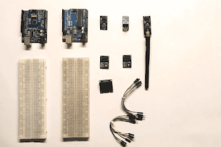
  1. Arduino Uno – x2

  2. nRF24L01 – x2

  3. 3.3V Adapter Board for nRF24L01 – x2

  4. DHT11 Temperature and Humidity Sensor

  5. OLED Display

  6. Breadboard – x2

  7. Jumper Wires

Understanding the nRF24L01 Module

The nRF24L01 is a compact 2.4GHz transceiver module designed by Nordic Semiconductor. It supports both transmitting and receiving data and communicates with microcontrollers over the SPI interface. This module operates on 3.3V and consumes very little power—about 12mA during data transmission. There are multiple versions of this module, including one with an external antenna and an onboard PA (Power Amplifier) and LNA (Low-Noise Amplifier) chip (RFX2401C), which greatly improves the communication range and reliability, especially in noisy environments.

3.3V-Adapter-Board-for-nRF24L01

Final Working and Testing

Once Code uploaded:

  • The transmitter reads temperature and humidity every 2 seconds.
  • The receiver gets the data and displays it on the OLED and Serial Monitor.
  • You can test the range indoors or outdoors to explore its full potential.
Applications of nRF24L01
  • Home automation
  • Wireless sensors
  • Remote-controlled robots.
In-depth Code and Project Tutorial : Interfacing nRF24L01 with Arduino UNO