Sunday 16 June 2024

Understanding Transformers: Types, Construction, and Applications


Transformers play a pivotal role in both electrical and electronics realms, harnessing the fundamental principles of electromagnetism pioneered by Michael Faraday. Let's delve into the world of transformers, exploring the diverse types of transformers, constructions, and the wide array of applications they serve.


Types of Transformers Based on Voltage Level


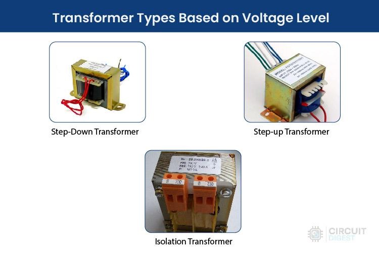
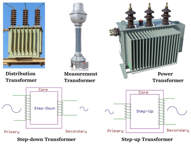
1. Step-Down Transformer

Step-down transformers are workhorses in electronics, converting high primary voltages to lower secondary voltages. You'll find them in everyday devices like power adapters and chargers, as well as in electrical systems for reducing high transmission voltages to usable levels.


2. Step-Up Transformer

Conversely, step-up transformers boost low primary voltages to higher secondary voltages. They're essential in stabilizers, inverters, and power distribution networks, enabling efficient transmission of high voltages over long distances.


3. Isolation Transformer

Isolation transformers maintain equal voltages on both primary and secondary sides, ensuring electrical safety and minimizing noise. They're a must-have in sensitive equipment setups to prevent interference.


Transformer Types Based on Core Material


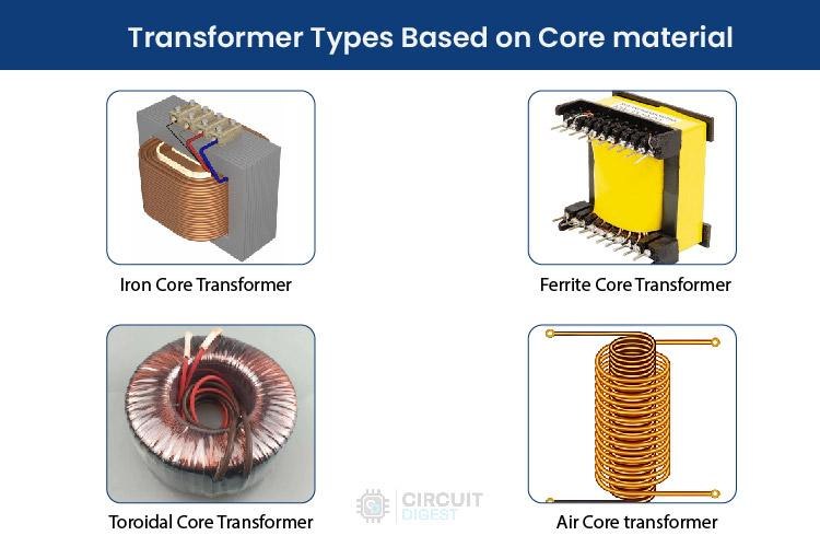
1. Iron Core Transformer

These transformers utilize soft iron plates, delivering high flux linkage and efficiency. They're commonly found in power applications, known for their robust but bulky construction.


2. Ferrite Core Transformer

Ferrite core transformers shine in high-frequency applications like switch-mode power supplies (SMPS) and RF circuits due to their low loss and high magnetic permeability.


3. Toroidal Core Transformer

With a doughnut-shaped core, toroidal transformers offer superior electrical performance with minimal leakage inductance. They're lightweight and more efficient compared to traditional transformers.


4. Air Core Transformer

Air core transformers, devoid of a physical core, rely on air for flux linkage. They're popular in portable electronics, RF applications, and wireless charging solutions.


Transformer Types Based on Winding Arrangement


Auto Winding Transformer

Auto transformers feature a single winding acting as both primary and secondary, with a movable center tap for adjusting output voltage. They're commonly used in voltage stabilizers and power distribution setups.


Transformers Based on Usage


Power Domain


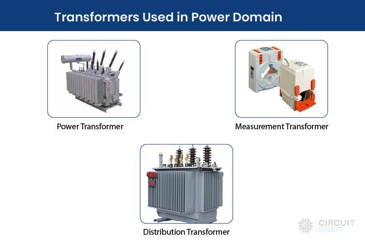
  • Power Transformer: Facilitates energy transfer in substations and grids, converting high current at low voltage to low current at high voltage for efficient distribution.

  • Measurement Transformer: Also known as instrument transformers, these devices isolate and convert current and voltage for accurate measurements.

  • Distribution Transformer: Step-down transformers that adjust grid voltage to levels required by consumers, typically seen in power lines.


Electronics Domain


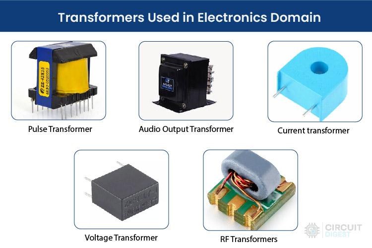
  • Pulse Transformer: Essential in digital circuits for generating isolated electrical pulses.

  • Audio Output Transformer: Balances amplifier circuits and loads in audio applications.

  • Current Transformer: Measures AC current, featuring a primary winding with a few turns or a bus bar.

  • Voltage Transformer: Measures AC voltage by stepping it down to a measurable level.

  • RF Transformers: Vital in radio and communication equipment for impedance matching and maintaining signal integrity at high frequencies.


Understanding the myriad types of transformers and their applications is essential for professionals in both electrical and electronics fields. Each transformer type, whether it's for stepping up voltage or ensuring electrical isolation, serves specific purposes in powering, measuring, and maintaining electronic systems, ensuring efficiency and safety across various domains.


Saturday 8 June 2024

Understanding Staircase Lighting with Two-Way Switches: A Practical Guide


One of the first practical projects young engineers encounter is the staircase lighting setup. This setup uses a 2 way switch wiring, allowing you to control a light from two different locations, ideal for staircases.


Components Required

  1. Two 2-way switches

  2. Bulb

  3. AC supply

  4. Connecting wires


Two-Wire Control Method

This older method connects the live wire to the common terminal of the first switch. The other terminals of both switches are cross-connected. The light connects to the second switch and is neutral. The light is off when switches are in opposite states, similar to an Ex-NOR gate.


Three-Wire Control Method


This modern method short-circuits the common terminals of both switches. One terminal of each switch connects to the live wire, and the other terminal to the lamp. The light is on when switches are in different states, akin to an Ex-OR gate.


Applications

  • Staircases

  • Large rooms with multiple entry/exit points

  • Controlling AC appliances from two locations


This setup provides a simple and effective solution for controlling lights in various scenarios.


For a detailed video tutorial, check out the link below: 2 Way Switch Wiring


Wednesday 5 June 2024

Explore the fundamentals of Full Adder circuits


Binary adders come in two types: Half Adders and Full Adders. A half adder adds 2-bit binary numbers but cannot include a carry bit. In contrast, a Full Adder adds the carry bit along with the two binary numbers, enabling the addition of multi-bit binary numbers by cascading multiple Full Adder circuits.


Full Adder Circuit

The main limitation of a half adder is the lack of a ‘Carry in’ bit. In a Full Adder circuit, we include a carry in input and add it to inputs A and B, giving us three inputs (A, B, and Carry In) and producing two outputs (SUM and Carry Out).


Full Adder Block Diagram

The Full Adder is constructed by combining two half-adder circuits and an OR gate. Here’s how it works:


  1. The first half-adder adds inputs A and B, producing SUM and Carry out.

  2. The SUM output from the first half-adder is fed into the second half-adder along with the Carry in bit.

  3. The final SUM output is the result of the Full Adder.

  4. The Carry out bits from both half-adders are combined using an OR gate to produce the final Carry out.


Construction of Full Adder Circuit

Here’s a step-by-step guide to constructing a Full Adder Circuit:


Components Needed

  • Two Half Adder circuits

  • OR Gate

  • Steps

  • Connect the inputs A and B to the first half-adder.

The SUM output from the first half-adder goes to the input of the second half-adder along with the Carry in bit.

The final SUM output from the second half-adder is the overall SUM output of the Full Adder.

Combine the Carry out bits from both half-adders using an OR gate to produce the final Carry out.


Circuit Diagram and Logic Gates

The full adder circuit utilizes XOR, AND, and OR gates. The two half adders are connected such that the first half adder handles inputs A and B, while its SUM output and the Carry in bit are fed into the second half adder. The OR gate then combines the Carry out bits from both half adders.


Truth Table of Full Adder Circuit

The truth table for the Full Adder circuit includes three inputs (A, B, Carry In) and two outputs (SUM, Carry Out):


The SUM output is obtained by XORing inputs A and B and then XORing the result with the Carry in bit. The Carry out is calculated by ORing the AND results of the input pairs.


Cascading Adder Circuits

To add multi-bit binary numbers, you can cascade Full Adder circuits, forming what’s known as a Ripple Carry Adder circuit. The Carry out from each Full Adder is connected to the Carry in of the next Full Adder, allowing the addition of larger binary numbers. However, this can introduce propagation delays, which can be mitigated using a carry look-ahead adder.


Practical Demonstration: Full Adder Using IC 74LS283N

To demonstrate a practical Full Adder, we use the IC 74LS283N, a 4-bit full adder with carry look-ahead features. Here’s a list of components required:

  • 74LS283N IC

  • 4-pin DIP switches (2 pcs)

  • Red LEDs (4 pcs)

  • Green LED (1 pc)

  • 4.7k resistors (8 pcs)

  • 1k resistors (5 pcs)

  • Breadboard

  • Connecting wires

  • 5V adapter


Circuit Setup

Connect the VCC and Ground to pins 16 and 8, respectively.

Connect the first 4-bit number to pins 5, 3, 14, and 12 (P inputs).

Connect the second 4-bit number to pins 6, 2, 15, and 11.

The SUM outputs will be on pins 4, 1, 13, and 10.

Use 4.7k resistors on all input pins to set logic 0 when switches are off.

Use red LEDs for SUM outputs and a green LED for the Carry out bit.

For a visual demonstration, check out the video tutorial below where we show adding two 4-bit binary numbers using the 74LS283N IC.


Understanding Full Adder circuits is crucial for digital electronics. By combining half adders and using logic gates, we can build efficient circuits for adding binary numbers, with applications ranging from simple calculators to complex computer systems.


Watch the detailed video tutorial here: Full Adder Circuit Tutorial.


Monday 3 June 2024

Calculating the Right Resistor for Your LED: A Step-by-Step Guide

Using an LED resistor calculator can help you determine the appropriate resistance for your LED circuit, ensuring your LEDs operate safely. Here's how to use one effectively.


Inputs

  • Source Voltage (Vs): The total voltage from your power source, measured in volts.

  • LED Forward Voltage (Vf): The voltage drop across the LED, which varies by color (e.g., Red = 2V).

  • LED Forward Current (If): The current flowing through the LED, typically around 20mA.

  • Number of LEDs in Series: How many LEDs are connected in a series configuration.


Outputs

  • Resistance (R): The value of the resistor needed, measured in ohms.

  • Resistor's Wattage (P): The power rating of the resistor, measured in watts.


Why Use a Resistor with LEDs?

LEDs require a specific range of current to operate correctly. Exceeding this range can damage the LED. A resistor in series with the LED helps limit the current to a safe level.


How to Use the Calculator

Input Values: Enter the source voltage (Vs), LED forward voltage (Vf), LED forward current (If), and the number of LEDs in series.

Calculate: The calculator will provide the necessary resistor value (R) and its power rating (P).

LED Forward Voltage by Color

Red: 2V

Green: 2.1V

Blue/White: 3.6V

Yellow: 2.1V

Orange: 2.2V

Amber: 2.1V

Infrared: 1.7V


Calculation Equation

To find the resistor value mathematically, use the equation:


LED resistor calculation

​Where:

Vs: Source voltage

Vf: LED forward voltage

If: LED forward current (in amps)

N: Number of LEDs in series


Using an LED resistor calculator simplifies finding the right resistor to ensure your LEDs work safely and efficiently. By inputting your circuit parameters, you can quickly get the necessary resistance value and avoid potential damage to your LEDs.


To use the calculator, visit: LED Resistor Calculator.