 In this RFID based Attendance System project, we will explain you how can we count attendance automatically by using RFID cards. RFID Tecnology (Radio Frequency Identification and Detection) is commonly used in schools, colleges, office and stations for various purposes to automatically keep a track of people. Here we will count the attendance of an authorised person by using RFID.
 In this project, we are going to make a Fire Alert System using ATMEGA8 microcontroller and fire sensor. Fire sensor can be of any type, however we are using IR (Infrared) based Fire Sensor. Although IR based Fire Sensors have some disadvantages mostly of inaccuracy, it is the cheapest and easiest way to detect fire.
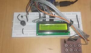 Security is a major concern in our day to day life, and digital locks have became an important part of these security systems. One such digital code lock is imitated in this project using arduino board and a matrix keypad.
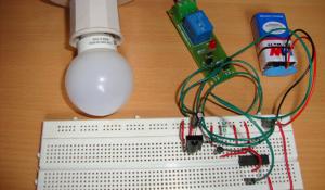 IR LED emits infrared light, and used in TV remotes. This Infrared is received by the receiver TSOP17XX (TSOP 1738used in TV). TSOP17XX receives the modulated Infrared waves and changes its output. TSOP is available in many frequency ranges like TSOP1730, TSOP1738, TSOP1740 etc. Last two digits represent the frequency (in Khz) of modulated IR rays, on which TSOP responds. Like for example TSOP1738 reacts when it receives the IR radiation modulated at 38Khz. TSOP output is active low, means it becomes LOW when IR is detected.
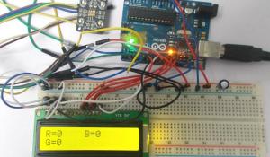 In this project we are going to interface TCS320 color sensor with Arduino UNO. TCS320 is a color sensor which can detect any number of colors with right programming. TCS230 contains RGB (Red Green Blue) arrays. As shown in figure on microscopic level one can see the square boxes inside the eye on sensor. These square boxes are arrays of RGB matrix. Each of these boxes contain Three sensors, One is for sensing RED light intensity, One is for sensing GREEN light intensity and the last in for sensing BLUE light intensity.
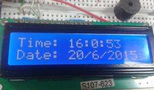 This Arduino based Real time clock is a digital clock to display real time using a RTC IC DS1307which works on I2C protocol. Real time clock means it runs even after power failure. When power is reconnected, it displays the real time inrespective to the time and duration it was in off state. In this project we have used a 16x2 LCD module to display the time in - (hour, minute, seconds, date, month and year) format.
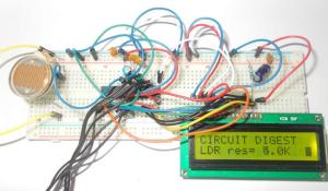 In this project we are going to interface LDR with ATMEGA8 microcontroller, and with this we can measure LIGHT INTENSITY in the area. In ATMEGA8, we are going to use 10bit ADC (Analog to Digital Conversion) feature to measure the light intensity.
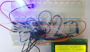 In this project we are going to make a low range ammeter using ATMEGA8 microcontroller. In ATMEGA8, we are going use 10bit ADC (Analog to Digital Conversion) feature to do this. Although we have few other ways to get the current parameter from a circuit, we are going to use resistive drop method, because it’s the easiest and simplest way to get current parameter.
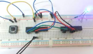 In this tutorial we are going to establish a serial communication between two ATMEGA8 microcontrollers. The communication established here is UART (Universal Asynchronous Receiver Transmitter) type. By this serial communication data can be shared between two microcontrollers, which is required in various embedded systems.
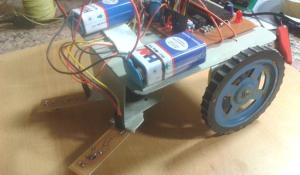 Line follower Robot is a machine which follows a line, it may be a black line or a white line. Basically two types of line follower robots are: one is black line follower which follows black line and second one is white line follower which follows white line. Line follower actually senses the line and run over it. In our previous projects, we have made a black line follower robot using arduino but this time we are going to make white line follower using 8051 microcontroller. In this tutorial, we will also cover how to make a printed circuit board for line follower robot at home in low price.
Check more interesting projects and circuits here: Electronics Projects