Showing posts with label ArduinoUno. Show all posts

Friday, 13 March 2026

DC Motor Speed Control Using GSM with Arduino – SMS-Based Motor Control

DC Motor Control Using GSM

Automation and remote control systems are becoming increasingly important in modern engineering. In many situations, operating machines manually is not always practical, especially in large industrial setups, agricultural fields, or remote locations. Remote control technologies help solve this problem by allowing devices to be operated from a distance without direct human interaction.

In this project, we build a DC motor speed control using GSM and Arduino. Instead of controlling the motor with physical switches, the motor can be operated remotely using SMS commands sent from a mobile phone. The Arduino receives these commands through a GSM module and controls the motor accordingly.

Components Required

This project uses several commonly available electronic components:

  • Arduino Uno
  • SIM800L GSM Module
  • L298N Motor Driver
  • DC Motor
  • Logic Level Shifter
  • Breadboard
  • Jumper Wires
  • External Power Supply
  • Arduino IDE
Components Required for the DC Motor Control Using GSM

The Arduino Uno acts as the main controller that processes incoming SMS commands and sends control signals to the motor driver. The SIM800L GSM module receives SMS messages from the user’s phone and forwards them to the Arduino. The L298N motor driver is responsible for controlling the speed and direction of the DC motor.

Because the GSM module and Arduino operate at different voltage levels, a logic level shifter is used to ensure safe communication between the two devices.

Circuit Overview

Circuit Diagram of DC Motor Control Using GSM

The circuit connects the Arduino, GSM module, motor driver, and motor together to create a complete control system.

The GSM module communicates with the Arduino through serial communication. When an SMS message is received, the module sends the message data to the Arduino. Since the SIM800L operates at a lower voltage level than the Arduino, a level translator is used to convert the signals safely.

The Arduino processes the received command and sends control signals to the L298N motor driver. The driver then supplies the required current to the motor and determines its direction and speed.

Motor direction is controlled through two input pins on the motor driver, while motor speed is controlled using Pulse Width Modulation (PWM) from the Arduino. A separate power supply is usually required for the motor and GSM module to ensure stable operation.

All components share a common ground connection, which is essential for proper communication between devices.

How GSM-Based Motor Control Works

The working principle of this system is simple and efficient.

When the circuit is powered on, the Arduino and GSM module are initialized. The GSM module connects to the mobile network and waits for incoming SMS messages. Meanwhile, the Arduino continuously monitors the serial interface for new data from the GSM module.

The user sends an SMS command from a mobile phone to control the motor. Each message contains a predefined command that represents a specific motor action.

For example:

  • FWD200 – Rotate the motor forward at speed level 200

  • REV150 – Rotate the motor in reverse at speed level 150

  • STOP – Stop the motor immediately

When the GSM module receives the SMS, it forwards the message content to the Arduino through serial communication. The Arduino reads the message and checks whether it matches one of the predefined commands.

If the command indicates forward rotation, the Arduino sets the input pins of the motor driver accordingly so the motor rotates in the forward direction. If the command indicates reverse rotation, the logic signals are reversed to change the direction.

For speed control, the Arduino generates a PWM signal on the enable pin of the motor driver. By changing the PWM duty cycle, the motor speed can be increased or decreased smoothly.

Using this method, the motor can be controlled remotely from anywhere within GSM network coverage.

Real-World Applications

GSM-based motor control systems have several practical applications.

  • Automated gates
  • Security barriers
  • Home automation systems 

Because GSM communication does not require internet connectivity, the system works reliably even in areas with limited internet access.

The DC motor speed control using GSM and Arduino project demonstrates a practical method for remotely controlling motors using SMS commands. By combining an Arduino Uno, SIM800 GSM module, and L298N motor driver, the motor’s speed and direction can be controlled without physical interaction.

This project also introduces important concepts such as GSM communication, PWM-based speed control, serial interfacing, and motor driver operation. With small modifications, the system can be expanded to control multiple motors or integrated into larger automation systems.

Overall, this project provides a simple and effective solution for remote motor control in real-world applications. 

https://circuitdigest.com 

Robotics Projects |Arduino Projects | Raspberry Pi Projects|

Thursday, 1 May 2025

How to use nRF24L01 module with Arduino


If you're looking to add wireless communication to your project, the Arduino and nRF24L01 module combo is one of the most reliable and cost-effective solutions available. Whether you're building a DIY spy bug, a long-range walkie-talkie, or just want to control devices wirelessly, the nRF24L01 lets you send and receive data over long distances using the 2.4GHz band. In this guide, you'll learn how to create your own wireless Arduino project using the nRF24L01 transceiver , complete with circuit diagrams and step-by-step instructions.


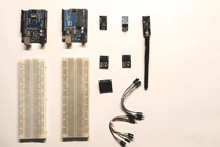
Components Required

  1. Arduino Uno – x2

  2. nRF24L01 – x2

  3. 3.3V Adapter Board for nRF24L01 – x2

  4. DHT11 Temperature and Humidity Sensor

  5. OLED Display

  6. Breadboard – x2

  7. Jumper Wires

Understanding the nRF24L01 Module

The nRF24L01 is a compact 2.4GHz transceiver module designed by Nordic Semiconductor. It supports both transmitting and receiving data and communicates with microcontrollers over the SPI interface. This module operates on 3.3V and consumes very little power—about 12mA during data transmission. There are multiple versions of this module, including one with an external antenna and an onboard PA (Power Amplifier) and LNA (Low-Noise Amplifier) chip (RFX2401C), which greatly improves the communication range and reliability, especially in noisy environments.

3.3V-Adapter-Board-for-nRF24L01

Final Working and Testing

Once Code uploaded:

  • The transmitter reads temperature and humidity every 2 seconds.
  • The receiver gets the data and displays it on the OLED and Serial Monitor.
  • You can test the range indoors or outdoors to explore its full potential.
Applications of nRF24L01
  • Home automation
  • Wireless sensors
  • Remote-controlled robots.
In-depth Code and Project Tutorial : Interfacing nRF24L01 with Arduino UNO

Monday, 20 May 2024

Easy Steps to Interface OLED Display With Arduino


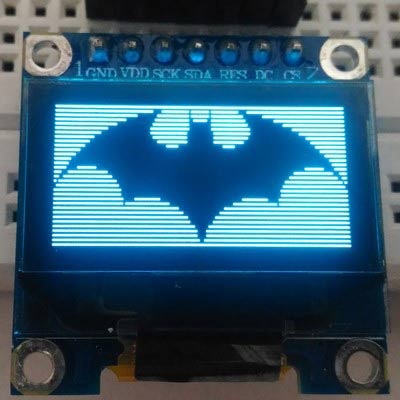
Are you tired of the limitations posed by traditional LCD displays in your Arduino projects? Say hello to Arduino OLED displays – the versatile, feature-rich alternative that opens up a world of possibilities for your creations. In this comprehensive guide, we'll delve into everything you need to know about OLED displays and how to seamlessly integrate them with your Arduino projects.


Understanding OLED Displays

OLED (Organic Light Emitting Diode) displays are a game-changer in the realm of visual interfaces. Unlike LCD technology, OLED displays are self-emissive, meaning each individual pixel generates its own light, eliminating the need for a backlight. This not only results in deeper blacks and vibrant colors but also enables thinner and more energy-efficient displays.


Types of OLED Displays

OLED displays come in various sizes, resolutions, and communication protocols, offering flexibility to suit diverse project requirements. The two primary communication protocols used are I2C and SPI, each with its own advantages in terms of speed and complexity.


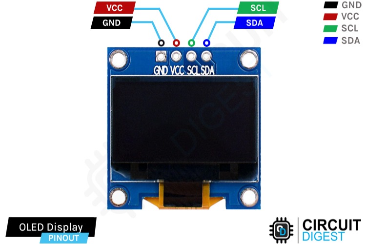
I2C OLED Display Module Pinout:


Ground (GND): Connect to the Arduino's ground pin.

Power (VCC): Provides power to the module (usually connected to the 5V pin).

Serial Clock (SCL): Generates clock pulses for I2C communication.

Serial Data (SDA): Transfers data via I2C communication.


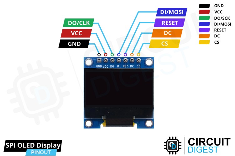
SPI OLED Display Module Pinout:


Ground (GND): Connect to the Arduino's ground pin.

Power (VCC): Provides power to the module (usually connected to the 5V pin).

Serial Clock (D0/CLK): Generates clock pulses for SPI communication.

Serial Data In (D1/MOSI): Sends data to the display.

Reset (RESET): Resets the internal buffer of the display.

Data/Command (DC): Controls the type of data sent to the display.

Chip Select (CS): Selects the display controller.


Interfacing with Arduino

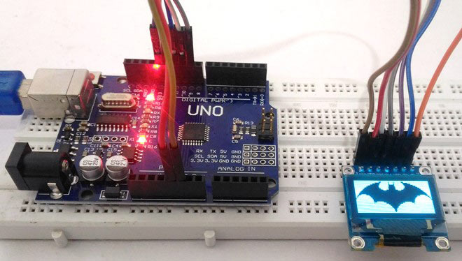
Connecting OLED displays to Arduino boards is straightforward, requiring minimal components and simple wiring. Whether using I2C or SPI interface, the process involves connecting power, ground, and communication pins according to the chosen protocol.


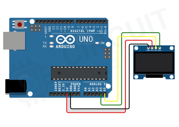
I2C OLED Module Interfacing Connection Diagram:


GND to GND pin

VCC to 5V pin

SCL to A5 pin

SDA to A4 pin


SPI OLED Module Interfacing Connection Diagram:


GND to GND pin

VCC to 5V pin

D0/CLK to digital pin 10

D1/MOSI to digital pin 9

RESET to digital pin 13

DC to digital pin 11

CS to digital pin 12


Programming OLED Displays

Once the hardware connections are established, programming OLED displays with Arduino involves installing the necessary libraries and writing code to control the display content. Whether using I2C or SPI, the Adafruit SSD1306 and Adafruit GFX libraries are essential for interfacing with OLED displays.


Basic Text and Graphics Functions

From displaying text and numbers to drawing shapes and images, OLED displays offer a myriad of possibilities for visual representation. Using functions provided by the Adafruit GFX library, you can manipulate text size, color, and position, as well as draw various shapes with ease.


Troubleshooting and Common Issues

While working with OLED displays, encountering issues is not uncommon. However, by following a systematic troubleshooting approach, you can quickly identify and resolve common problems related to hardware connections, power supply, code errors, and display settings.


In conclusion, OLED displays present a versatile and powerful solution for visual interfaces in Arduino projects. By understanding the different types of OLED displays, mastering their interfacing with Arduino, and leveraging the rich set of programming functions, you can unlock endless possibilities for creativity and innovation in your projects.


Check out our comprehensive video tutorial on integrating OLED displays with Arduino


Sunday, 7 April 2024

Troubleshooting Guide: Interfacing SIM800L with Arduino

If you've ever worked with the SIM800L module (Arduino GSM), you know it's a versatile tool for a variety of projects, from making calls to sending SMS and accessing the internet via GPRS. However, like any tech, it has its quirks. In this article, we'll guide you through interfacing the SIM800L with Arduino and offer troubleshooting tips to ensure smooth operation. Plus, we'll touch on our experience with the SIM800L on ESP32 if you're curious.


Understanding SIM800L Module Pinout:

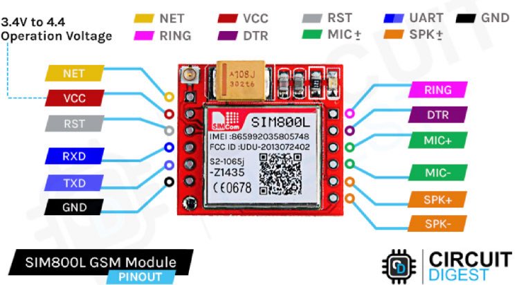
The SIM800L module, a GSM/GPRS module, features various pins serving distinct functions critical for its operation. Among these pins, VCC provides the power supply, while GND serves as the ground connection. TX and RX facilitate data transmission and reception, enabling communication with other devices. Understanding the pinout is essential for correctly connecting the module to other components in the system.


Powering the SIM800L GSM Module:

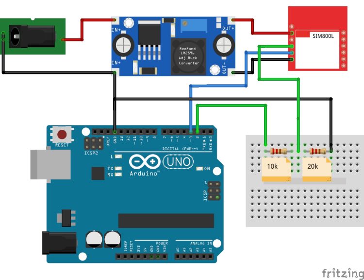
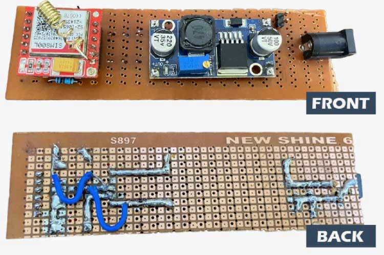
Powering the SIM800L module requires a stable power supply within the range of 3.7V to 4.2V. Achieving this can be accomplished using a buck converter with a minimum current capacity of 2A or a 3.7V Li-ion battery. Additionally, adding a capacitor between VCC and GND can enhance power stability, although it's not mandatory for basic functionality.


Interfacing SIM800L with Arduino UNO:

Interfacing the SIM800L with an Arduino UNO necessitates addressing voltage compatibility issues. While the SIM800L operates at 3.3V, the Arduino UNO internally operates at 5V. To bridge this voltage discrepancy safely, a voltage divider calculator is typically employed, utilizing resistors to generate a 3.3V signal from the Arduino's 5V output.


Troubleshooting SIM800L Issues:

Common issues encountered with the SIM800L module include challenges with SIM card detection and network connectivity. The LED indicators on the module offer valuable insights, such as network status, aiding in the troubleshooting process. Steps for troubleshooting involve verifying correct SIM card insertion, ensuring a stable power supply, and checking for adequate network coverage.


SIM800L AT Command Testing:

AT commands are instrumental in communicating with the SIM800L module and executing various functions. By uploading an SIM800L AT command test program to the Arduino, direct communication with the module is established. Sending AT commands and interpreting the responses allows for the verification of the module's responsiveness and functionality.


Sending SMS and Making Calls:

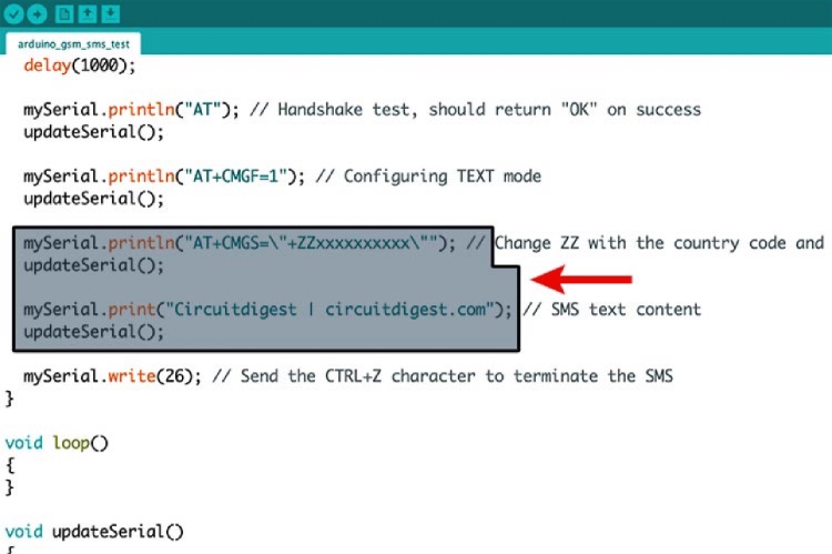
Upon confirming the responsiveness of the SIM800L module, exploring its features such as sending SMS and making calls becomes feasible. Sample Arduino code is available for executing these actions, accompanied by detailed explanations of each step in the process. These functionalities broaden the scope of potential applications, enabling communication capabilities within projects.


Conclusion:

Mastering the intricacies of the SIM800L module empowers individuals to leverage its capabilities effectively in various projects. Understanding the module's pinout, power requirements, and troubleshooting techniques facilitates overcoming challenges that may arise during implementation. Furthermore, exploring additional projects, such as SMS-based vehicle tracking and forest fire warning systems, fosters ongoing learning and innovation in utilizing the SIM800L module.