Sunday 30 August 2015

Demonstration of Logic Gates

NOT Gate
NOT gates are simply inverters. They simply invert the input logic for the output. Here we are going to use 74LS04 IC for demonstration. This IC has 6 NOT gates in it. These SIX gate are connected internally.
Here is the breadboard image of a NOT gate circuit.

You can find the explanation of this circuit: NOT Gate Circuit

NAND Gate
This gate is mainly used in applications where there is a need for mathematical calculations. So calculators, computers and many digital applications use this gate. 

Here you can find the circuit diagram and detailed explanation of this Circuit: NAND Gate

XOR Gate
This gate is mainly used in applications where there is a need for mathematical calculations. So in calculators, computers and many digital applications use this gate.
Here we are going to use 74LS86 IC for demonstration, this chip has 4 EX-OR gates in it.


Wednesday 26 August 2015

Reverse Car Parking Aid - Circuit Diagram

This reverse car parking assistant can protect your car from any damage while reverse parking. Though modern cars incorporate various reverse car parking sensors and cameras, this hobby circuit could be interesting and handy for many of us. It indicates the distance of car from any object and raise an alarm when it reaches close to the wall or the object and needs to be stopped. .

Here are the quick easy steps and a detailed explanation to understand the concepts and working of this circuit.


Friday 21 August 2015

Battery Monitor Circuit Diagram


Sometimes we face a common problem when making any project related to battery or power supply - we don’t know about battery is charged or discharged. To test battery there is one common method which is using voltmeter that is available in the Multimeters. But here we have developed this battery monitor circuit to test the battery charging status. In this circuit we can easily test batteries by connecting it with the circuit. Here some LEDs are used for showing battery status.
Check out more details here: Battery Monitor Circuit


Sunday 9 August 2015

Basic tutorials to get started with arduino

Here are few basic arduino tutorials to learn working with the board.
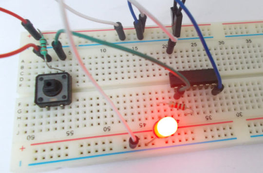
1. How to blink an LED with Arduino:
ARDUINO UNO is an ATMEGA controller based board designed for electronic engineers and hobbyists. Arduino based program development environment is an easy way to write the program when compared to other environment development programs. Check out the tutorial to learn how to blink an LED with arduino uno board.

In this tutorial we are introducing concept of ADC (Analog to Digital Conversion) in ARDUINO UNO. Arduino board has six ADC channels, as show in figure below. Among those any one or all of them can be used as inputs for analog voltage. The Arduino Uno ADC is of 10 bit resolution (so the integer values from (0-(2^10) 1023)). This means that it will map input voltages between 0 and 5 volts into integer values between 0 and 1023. So for every (5/1024= 4.9mV) per unit.

In this tutorial we are going to interface a seven segment display to ARDUINO UNO. The display counts from 0-9 and resets itself to zero.

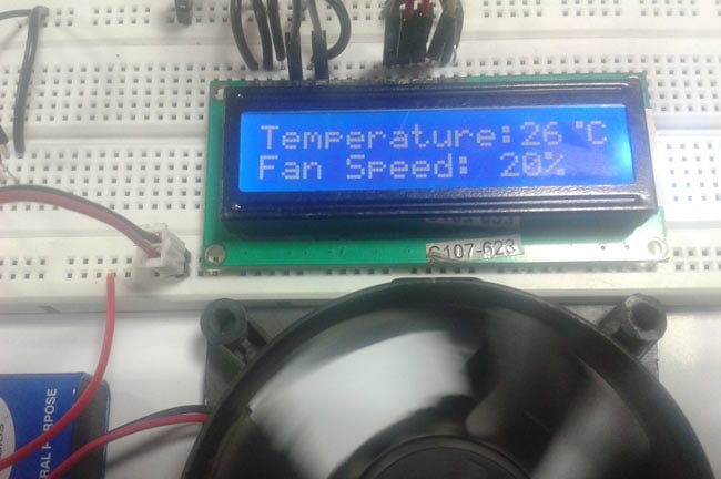
In this tutorial we are going to interface a 16x2 LCD with ARDUINO UNO. Unlike normal development boards interfacing a LCD to a ARDUINO is quite easy. Here we don’t have to worry about data sending and receiving. We just have to define the pin numbers and it will be ready to display data on LCD.

Now for some applications we need more than 30 pins, say if we want to design a 5x5x5 LED CUBE, so for this we need 5x5+5=30pins. For such cases we use serial to parallel converter chips or shift register. A shift register chip takes data from UNO board serially and gives output in 8 bit parallel configuration.

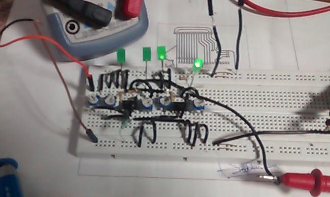
Arduino UNO has 6PWM channels, so we can get PWM (variable voltage) at any of these six pins. In this chapter we are going to use PIN3 as PWM output.

Here we are going to interface a DC motor to Arduino UNO and its speed is controlled. This is done by PWM (Pulse Width Modulation). This feature is enabled in UNO to get variable voltage over constant voltage.

For more such basic arduino tutorials and interesting projects, visit circuitdigest.com


Tuesday 4 August 2015

Automatic Fan Speed Control according to Temperature


In this arduino based project, we are going to control DC fan speed according to the room temperature and show these parameter changes on a 16x2 LCD display. It is accomplished by the data communications between Arduino, LCD, DHT11 sensor Module and DC fan that is controlled by using PWM.

Video: