Thursday 29 February 2024

How to Interface MAX30102 Pulse Oximeter with Arduino?

 In today's era of wearable technology and health monitoring devices, the MAX30102 Pulse Oximeter and Heart Rate Sensor have emerged as a crucial component. Developed by Analog Devices, this sensor offers a compact yet powerful solution for tracking heart rate, blood oxygen levels, and even body temperature.

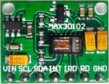
At its core, the MAX30102 sensor utilizes advanced technology, including two LEDs (Infrared and Red), a photodetector, and sophisticated signal processing algorithms. By emitting light through the skin and analyzing the reflected light, the sensor can derive essential physiological data, such as heart rate and blood oxygen levels.


The operational principle of the MAX30102 sensor is straightforward yet effective. By measuring the absorption of light at specific wavelengths, the sensor can detect changes in blood oxygen levels and heart rate. This capability has significant implications for various applications, including fitness tracking and medical diagnostics.


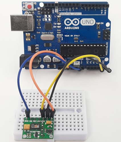
The integration of the MAX30102 sensor with Arduino opens up new possibilities for developers and hobbyists. By connecting the sensor to Arduino, users can leverage its capabilities to create innovative projects and applications. The sensor's I2C interface simplifies communication, while its low power consumption makes it suitable for battery-powered devices.


One notable feature of the MAX30102 sensor is its versatility. In addition to heart rate and blood oxygen level monitoring, it can also measure body temperature, expanding its utility across different domains.


Despite its compact size, the MAX30102 sensor delivers impressive performance. With a maximum current draw of 600μA during operation and a standby mode consumption of just 0.7μA, the sensor strikes a balance between efficiency and functionality.


Incorporating the MAX30102 sensor into Arduino projects is a straightforward process. By following the provided pinout and connection guidelines, users can quickly set up the sensor and start collecting data. The sensor's compatibility with Arduino libraries further simplifies development, enabling rapid prototyping and experimentation.


However, it's important to consider certain factors when working with the MAX30102 sensor. For example, users must ensure precise pull-up resistor values for optimal performance, and they should verify compatibility between sensor variants and corresponding Arduino libraries.


In summary, the MAX30102 Pulse Oximeter and Heart Rate Sensor represent a significant advancement in health monitoring technology. By harnessing its capabilities alongside Arduino, developers can create innovative solutions for a variety of applications, from wearable fitness trackers to remote health monitoring systems. With its compact design, low power consumption, and robust performance, the MAX30102 sensor is poised to drive advancements in health monitoring technology and beyond.


Here are some project ideas using the Arduino Pulse Oximeter and Heart Rate Sensor Module


Explore these projects to create innovative solutions for monitoring pulse and oxygen saturation levels.


Wednesday 28 February 2024

Understand Ohm's Law and Convert Volts to Ohms

 To comprehend the conversion of volts to ohms, it's crucial to grasp the fundamentals of Ohm's Law. Ohm's Law elucidates the relationship between voltage, current, and resistance in an electrical circuit, expressed as V = IR, where V denotes voltage (measured in volts), I represents current (measured in amps), and R signifies resistance (measured in ohms).

To determine resistance (R), we rearrange the formula to solve for R, resulting in R = V / I. By inputting the measured values into the formula, we can calculate the resistance. This method allows us to ascertain the resistance of an electrical component or circuit, given the voltage across it and the current flowing through it, using Ohm's Law.

In a practical demonstration utilizing an Ohm's Law simulation, we observe a circuit comprising a voltage source, a switch, a variable resistor, and a lamp as a load. Additionally, an ammeter and a voltmeter are included for easy measurements. By running the simulation, we observe changes in resistance and current, enabling us to verify Ohm's Law principles. For instance, altering the resistance value results in corresponding changes in current and voltage, affirming the application of Ohm's Law to calculate these electrical parameters.


Through this technique, we can ascertain any of the three values – voltage, current, or resistance – with knowledge of the other two, facilitating a deeper understanding of Ohm's Law and its practical implications in electrical engineering.

Ultimately, a thorough understanding of Ohm's Law empowers engineers to make informed decisions and solve complex electrical problems effectively, making it an indispensable tool in the field of electrical engineering.

Here is a convenient Ohm’s Law Calculator for performing these calculations.


Monday 26 February 2024

Understanding Soil Moisture Sensors: Benefits, Applications, and Integration with Arduino and IoT


Maintaining optimal soil moisture levels is essential for healthy plant growth. However, accurately determining water needs can be challenging, especially with diverse plant collections or varying water requirements. Soil moisture sensors offer a reliable solution for monitoring soil hydration, aiding growers in proper irrigation practices. In this article, we'll explore soil moisture sensors, covering their functionality, applications with Arduino and IoT technology, and integration into various circuits and systems.


Benefits of Utilizing Soil Moisture Sensors:


  • Prevents Overwatering: Overwatering, a common mistake, can lead to root rot and plant diseases. Sensors help target watering only when necessary, preventing detrimental effects and promoting healthy growth.

  • Optimizes Plant Growth: By providing the correct water amount, sensors ensure optimal conditions for plant health and growth. They can also assist in identifying areas prone to drying out or retaining excessive moisture.

  • Enhances Efficiency and Sustainability: By watering only when the soil demands it, sensors offer time and water conservation benefits, particularly valuable for busy individuals and those prioritizing eco-friendly practices.


How to Use Soil Sensor with Arduino:


Soil moisture sensors measure the water content in soil by detecting changes in electrical conductivity. This is achieved through probes inserted into the soil, which measure the resistance between them. As soil moisture increases, the conductivity rises, resulting in a decrease in resistance. This change is then translated into data that can be read by microcontrollers like Arduino. By connecting soil moisture sensors to Arduino, users can automate irrigation systems based on real-time soil moisture readings, ensuring optimal water usage for plant growth.


Smart Water Quality Monitoring System Using IoT:


Integrating soil moisture sensors with IoT technology enables real-time monitoring of soil moisture levels and water quality factors such as pH and conductivity. This allows for comprehensive data collection and analysis, facilitating informed decision-making in irrigation practices. By utilizing IoT-based smart water quality monitoring systems, users can optimize water usage, prevent overwatering, and promote sustainable agricultural practices.


Simple Soil Moisture Detector Circuit:

For those looking for a basic and cost-effective solution, a simple soil moisture detector circuit can be constructed using basic electronic components. This circuit measures the electrical conductivity of the soil and provides a visual indication, such as an LED turning on or off, to alert users to the need for watering. While offering limited functionalities, this DIY approach can serve as a valuable tool for basic soil moisture monitoring and learning purposes.


Soil Moisture Sensor and ESP8266 NodeMCU:

The integration of soil moisture sensors with microcontrollers like ESP8266 NodeMCU enables the creation of smart irrigation systems that automate watering based on real-time sensor readings. This approach optimizes water usage and minimizes manual intervention, promoting sustainable irrigation practices. By leveraging the power of IoT technology, users can remotely monitor soil moisture levels and adjust irrigation schedules as needed, leading to improved plant health and resource management.


Low Power IoT-Based Compact Soil Moisture Monitoring Device:

In remote or outdoor locations where power sources may be limited, low-power IoT-based compact soil moisture monitoring devices offer an efficient solution. These devices utilize IoT technology to enable easy deployment and data transmission with minimal power consumption. By providing accurate and timely soil moisture data, these devices contribute to informed decision-making in agricultural and environmental management, even in challenging environments.


Conclusion:

Soil moisture sensors are invaluable tools for monitoring soil hydration levels and optimizing water usage in various applications, from agriculture to environmental management. By understanding how these sensors work and exploring their diverse applications with Arduino and IoT technology, users can harness their potential to improve plant health, conserve water resources, and promote sustainable practices in soil management.


Thursday 22 February 2024

Popular Raspberry Pi Projects | Full Tutorial with Code and Circuit Diagram

Raspberry Pi – a small, but mighty computer that fits in the palm of your hand, complete with the ability to connect to a monitor, keyboard, and mouse. It's affordable and super easy to use, even if you're not a tech whiz. Whether you're a kid or an adult, Raspberry Pi is designed for everyone to have fun while learning about computers and technology. It's capable of doing all sorts of cool things, like teaching you how to code, helping you build your own games, creating smart home gadgets, and even making your own robots. The possibilities are endless.

The main objective of this article is to showcase the practical applications of Raspberry Pi and provide detailed tutorials through informative articles. Let’s get going…


DIY Raspberry Pi Motor Driver HAT


A Raspberry Pi HAT is an add-on board for Raspberry Pi with the same dimensions as Pi. There are many Raspberry Pi HATs available in the market. In this tutorial, we are going to build a Raspberry Pi Motor Driver HAT to drive DC and Stepper motors. This HAT features an L293D motor driver IC, a 16x2 LCD Display Module, four push-buttons, and additional pins for a SIM800 Module with a 3.3V regulator, making it perfect for robotics projects and so on…


Raspberry Pi CCTV Monitoring


If you do not have a CCTV installed, you can still build a Raspberry Pi Surveillance system by connecting USB cameras directly to your Pi. Create a versatile motion detection system for CCTV surveillance using OpenCV and Raspberry Pi. Additionally, include an alarm feature – a buzzer – to alert the user with a beep upon detecting activity. Know more about the Setting up of Raspberry Pi and OpenCV for monitoring.


Push-Up Counter using Raspberry Pi 


Be ready to track your progress seamlessly. Simply follow our step-by-step tutorial to set up the system, and start counting your push-ups with a Raspberry Pi 4 and Pi camera module, along with OpenCV and MediaPipe installed…. Using Raspberry Pi and MediaPipe Pose estimation package, you can accurately count push-ups in real-time, making your workouts more efficient.


Thermal Printer with Raspberry Pi


Learn how to interface a Thermal Printer with Raspberry Pi using hardware serial communication, to print a test receipt that contains various elements like a Logo, a QR Code, or barcode along with various other text and graphical characters. This project offers a practical and versatile solution for printing receipts, tickets, and more. Check out the full tutorial for step-by-step instructions… and start printing with Raspberry Pi 


Door Lock System using Raspberry Pi


The Captiosus System: an RFID-based door lock and entry system designed to offer enhanced security and convenience for homes and other premises. This system utilizes RFID tags as keys, allowing for controlled access through an RFID scanner. Additionally, it features an alarm system to deter unauthorized entry attempts.

Complete Tutorial- https://circuitdigest.com/microcontroller-projects/rfid-based-door-lock-system


 Raspberry Pi based Autonomous UV Robot


The autonomous UV robot project offers a cost-effective solution for disinfection needs, featuring a range of components like Raspberry Pi, Arduino UNO, and UV lights. It utilizes state-of-the-art SLAM technology for safe navigation, ensuring workers are not exposed to harmful UV light. With built-in sensors and wireless connectivity, the robot provides real-time status updates via a mobile app.


Complete Tutorial- Autonomous UV Robot with SLAM


Raspberry Pi Internet Radio and Streaming Station


Setting up a Raspberry Pi streaming station, You'll need a Raspberry Pi, a USB microphone, and an Internet connection. After updating your Pi, you'll install and configure DarkIce and Icecast, then test the setup via web browser access.

This tutorial demonstrates setting up a Raspberry Pi streaming station using DarkIce and Icecast. 


We hope you found this tutorial helpful and enjoyable. If you have any questions or comments, please leave them in the comment section below. Additionally, you can visit our website for technical assistance and to explore our latest project.


Friday 16 February 2024

ESP32 Projects with Circuit Diagram and Code | Full tutorials

 The ESP32 microcontroller, developed by Espressif Systems, is an exciting platform to learn about embedded systems and IoT (Internet of Things) technologies. At its core, the ESP32 is a small but powerful computer that can be programmed to perform a wide range of tasks, from controlling lights in a smart home to monitoring environmental conditions outdoors. Featuring built-in Wi-Fi and Bluetooth connectivity, as well as a dual-core processor and various input/output pins, the ESP32 can be adapted to suit many different projects and applications. This makes it an ideal tool for those who want to gain hands-on experience with real-world electronics and programming. 

Throughout this guide, we'll explore some projects that you can build using the ESP32 microcontroller. These articles will cover a variety of topics. Whether you're a beginner who's just getting started with electronics or an experienced hobbyist looking for new challenges, the ESP32 offers something for everyone. Let’s begin…


A Simple ESP32 LED Webserver


ESP32 LED web server from scratch - This project involves creating a web server on the ESP32 microcontroller, serving a web page to client devices over Wi-Fi. The page includes controls to toggle the LED lights on or off. Follow step-by-step instructions to set up the ESP32, connect LEDs, and create a web interface for control.


Designing a Smart Watch Using ESP32


Learn to build a smartwatch with the ESP32 microcontroller. Follow steps to assemble hardware, set up software, and customize features. Use ESP32's connectivity and sensors for functions like data tracking. With basic components like microcontrollers, sensors, and displays, create a personalized device. Experiment with Arduino coding for unique features such as button inputs and sensor data processing.


Power Consumption Monitoring Device


Create a simple power consumption monitoring device using an ESP32 and commonly available sensors. By detecting voltage and current draw, this DIY project allows you to monitor the energy consumption of electrical appliances in real-time. The ESP32 processes data from the sensors and displays energy consumption on the OLED display.


Smart Wi-Fi Video Doorbell using ESP32-CAM


To build a Smart Wi-Fi Doorbell using an ESP32-CAM module, which allows for remote monitoring and interaction with visitors. Utilizes IoT technology to perform actions such as playing a designated song on a smartphone and sending a text message containing a link to a live video stream whenever the doorbell button is pressed. To assemble the doorbell, you'll need components such as the ESP32-CAM module, an FTDI programming board, a 220V AC to 5V DC converter, a buzzer, a push button, and LEDs.


Full Tutorial: DIY Smart Wi-Fi Video Doorbell using ESP32 and Camera (circuitdigest.com)


Heart Rate Monitor using ESP32


It's important to monitor the pulse rate of patients, in this project we utilize a MAX30100 Pulse oximeter and an ESP32 microcontroller to create a Wi-Fi-enabled pulse oximeter. The device tracks blood oxygen levels and sends the data over the internet.


Full Tutorial: 
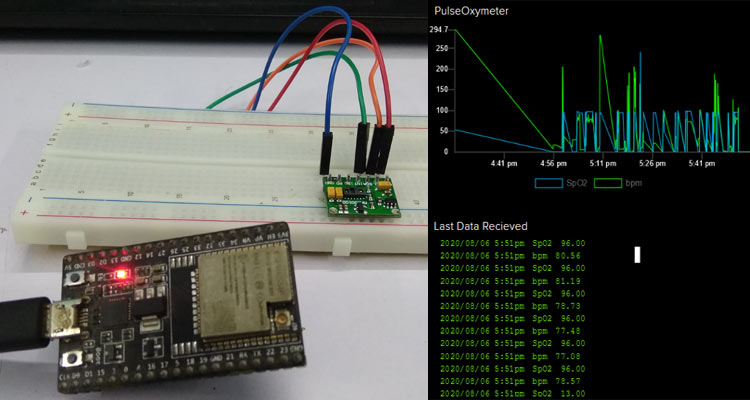
IoT Based Heart Rate Monitor using MAX30100 Pulse Oximeter and ESP32 (circuitdigest.com)


Security Camera using ESP32


This tutorial guides users through constructing a CCTV Security Camera using an ESP32 camera module, offering detailed steps from hardware setup to remote access configuration. The required components include an ESP32 CAM, FTDI programmer, jumper wires, and acrylic cut body parts.


Full Tutorial: How to build your own CCTV Security System: Step-by-Step DIY Guide (circuitdigest.com)


Wednesday 14 February 2024

Manual Techniques for Controlling Multiple Servos


The PCA9685 16-channel 12-bit PWM/Servo Driver module provides precise control over multiple PWM outputs, making it ideal for applications requiring accurate control over servos, LEDs, and various devices. This project aims to explore its functionalities, particularly focusing on how to control servo motors, to offer users a comprehensive understanding of its capabilities.

Required Components:

  • Arduino Uno R3
  • 8 * SG90 Servo Motors
  • PCA9685 16-Channel Module
  • External 5v Adapter
  • Jumper Wires

Interfacing Servo with Arduino:

Servo motors utilize PWM signals for precise control over their rotation angle. They typically feature three wires: VCC for power, GND for ground, and PWM for control signals. Connecting a servo to an Arduino involves supplying power and linking the PWM wire to a digital PWM pin. The Servo.h library enables servo control by uploading the Sweep Sketch to the Arduino IDE.

Arduino's limited number of PWM output pins poses challenges for scenarios requiring control over multiple servos. Complex techniques like multiplexing or software PWM may not offer accurate servo control. The PCA9685 module effectively addresses this limitation.

The PCA9685 module simplifies servo control by providing 16 free-running PWM outputs using only two pins, operated through I2C communication. It supports a wide range of applications, including robotics, automation, and lighting control. The module's features, such as a built-in clock and compatibility with 3.3V microcontrollers, enhance its versatility.

Programming the PCA9685 with Arduino:

Utilizing the Adafruit_PWMServoDriver library facilitates easy control of the PCA9685 module. By initializing the module and setting the PWM frequency, servo control becomes straightforward. The setPWM() function allows for precise control over servo angles, enabling smooth and synchronized motion. Prior to powering the setup, thorough checking of connections is crucial. Eight servos are connected to channels 0 to 7 of the PCA9685 module, powered by an external adapter for sufficient power. Monitoring angle and pulse data through the serial display provides insights into servo motion.

In summary, the PCA9685 16-Channel Servo Driver module offers a practical solution for precise control over multiple PWM outputs, particularly suited for applications involving servo motor control. Throughout this project, we've explored its functionalities, including interfacing methods and programming with Arduino. 


Tuesday 13 February 2024

Decode Counter: A Simple Counter for LED Projects


The CD4017 is a versatile decade counter/divider IC widely employed in counting applications and LED projects due to its 10 decoded outputs. It operates within a voltage range of 3V to 15V and features pins for output, ground, carry out, clock enable, clock, reset, and supply voltage. Available in both through-hole and SMD packages, it offers high-speed CMOS counting and TTL compatibility with a maximum clock frequency of 5.5MHz. Commonly used alongside LED matrices and chasers, it functions as a binary counter or decoder and facilitates divide-by-N counting. The IC incrementally counts from 0 to 9 upon receiving clock pulses, resetting to 0 after reaching 9. It allows for control over counting behavior via clock enable and reset pins, with the carry out pin signaling completion of counting. Its applications span LED projects, binary decoding, and remote metering in various industries.

Refer for detailed explanation about CD4017 - CD4017 IC Pinout, Description, Equivalents & Datasheet (components101.com)


Sunday 11 February 2024

Basics of Bipolar Junction Transistors in Electronic Circuits

Transistors are super important in electronic circuits, from basic ones to more complex ones. Bipolar Junction Transistors (BJTs) are a big part of this. They're like switches controlled by electricity. They have three parts: emitter, collector, and base. BJTs control how electricity flows between the emitter and collector based on the electricity sent to the base. They're shown as NPN or PNP symbols, depending on how they're set up inside.


BJTs work like switches or boosters. When you give a little electricity to the base, it lets a bigger flow of electricity from the collector to the emitter, turning the transistor on. They can be set up in different ways—Common Base (CB), Common Emitter (CE), and Common Collector (CC)—and each way affects how they handle electricity. BJTs are good for boosting electricity and turning things on and off quickly, but they use more power and can get hot.

Field Effect Transistors (FETs) are another type, and they work a bit differently. They're good for some things BJTs aren't, like using less power. BJTs are used in lots of circuits, like ones that do math, boost sound, or control time. They come in different packages to fit different needs. Overall, BJTs are a big part of electronics, helping circuits do lots of cool stuff, but they need to be used carefully to avoid problems.

For more detailed information on how Bipolar Junction Transistors (BJTs) work and their applications, you can check out the full article - BJT Transistors: Symbol, Basics, Construction, Working & Applications (components101.com)


Friday 9 February 2024

Understanding the Variants and Applications of BC557 Transistors

The BC557 transistor, commonly used in electronic circuits, offers versatility for amplification, switching, and voltage regulation purposes. Featuring three pins - collector, base, and emitter - it handles current flow and biasing control effectively. Key specifications include a maximum DC current gain of 300 and a continuous collector current of 100mA, making it suitable for various applications. Equivalents like BC157, BC558, and 2N3906 offer flexibility in circuit design.


Operating as a PNP transistor, the BC557 conducts when the base pin is grounded and cuts off when a signal is applied. With a gain range of 110 to 800, it amplifies signals efficiently while maintaining a maximum collector current of 100mA. This transistor serves as a switch or amplifier, depending on the circuit configuration, with common setups including common emitter, common collector, and common base.

Different versions of the BC557 transistor, such as BC557A, BC557B, and BC557C, offer varied gain ranges, addressing diverse amplification requirements. These transistors find common usage in driver modules like relay drivers, amplifier modules such as audio amplifiers, and in Darlington pairs to enhance overall performance.

Also, you can refer the Basics of BJT and How to use them.


Wednesday 7 February 2024

What are the different types of Fuse and Where to use them?


A fuse is a special device used in electrical circuits to protect them from damage caused by too much electric current. It works by containing a material that can melt when the current passing through it becomes too high. This melting breaks the circuit, stopping the flow of electricity and preventing further damage. There are different types of fuses for different types of circuits, like those used in homes, cars, and even in high-voltage power lines.

Fuses are divided into two main categories: AC and DC fuses. AC fuses are used in circuits where electricity flows back and forth in a specific pattern, like what we use in our homes. DC fuses, on the other hand, are used in circuits where electricity flows in only one direction, like in batteries or solar panels. Understanding how fuses work and the different types available helps to keep electrical systems safe and working properly.  Learn more information about fuses through the provided article -  different types of Fuse 


Proximity Sensors: Types and Applications

Proximity sensors are important tools used in industries to detect the presence of objects without needing physical contact. They serve various purposes, including enhancing automation, safety, and efficiency in different applications.


These sensors come in several types:

Inductive Proximity Sensors: Detect metal objects by using electromagnetic induction. They find applications in position sensing, object detection, and automated machinery.

Capacitive Proximity Sensors: Identify a wide range of materials, including conductive and non-conductive substances, by measuring changes in electrical capacitance. They are used in level sensing, liquid detection, and object proximity sensing.

Ultrasonic Proximity Sensors: Utilize sound waves to detect objects and measure their distance by analyzing the time it takes for sound waves to bounce back. They are effective in presence detection, level sensing, and collision avoidance systems.

Photoelectric Proximity Sensors: Use light to detect the presence or absence of objects. They come in various types such as through-beam, retro-reflective, and diffuse reflective, and are widely used in conveyor systems, packaging, and object counting applications.

Magnetic Proximity Sensors: Identify the presence of objects by detecting changes in magnetic fields. They are commonly used in speed sensing, door position detection, and security systems.

Each type of sensor operates differently and has its own unique applications, contributing to the efficiency and safety of industrial processes. Check out the given link to know much more about the different types of proximity sensor.


Monday 5 February 2024

Understanding the Types of Battery, It’s Chemistry, and Selection for Everyday Applications

Batteries are everywhere in our daily lives, powering devices like watches, toys, and even electric vehicles. There are two main types: primary, which you can't recharge, and secondary, which you can recharge.


Primary batteries, such as alkaline ones, are used in things like remote controls and pacemakers. They are convenient for devices that don't need a lot of power. On the other hand, secondary batteries, like the ones in phones and electric cars, can be charged and used again. They are suitable for devices that need a lot of power.

There are different kinds of rechargeable batteries, each with its own strengths. For example, Nickel-Cadmium batteries are good for electric vehicles, while Nickel-Metal Hydride batteries are used in high-drain devices. Lead-Acid batteries are reliable and used in things like solar panels, while Lithium-ion batteries are common in phones and gadgets.


Choosing the right battery depends on factors like how much energy it can hold, how quickly it can release that energy, and how safe and durable it is.

Here the detailed explanation about the battery and its types - Different Types of Batteries and their Applications (circuitdigest.com)


Ohm's Law: Formulas, Examples, and Calculator

Ohm's Law, named after the scientist Georg Simon Ohm, defines the relationship between Voltage (V), Current (I), and Resistance (R) in circuits. It states that electric current (I) is directly proportional to voltage (V) and inversely proportional to resistance (R).


Key Points:

  • Formulas: V = IR, I = V/R, R = V/I
  • These formulas enable calculations for voltage, current, resistance, and power (P).
  • Illustration: Two circuits with 12V source and different resistances show Ohm's Law in action.
  • Calculation Example: For a 110Ω circuit, I ≈ 0.11A; for a 220Ω circuit, I ≈ 0.5A.

Click the link to use the Ohm's Law Calculator - Ohm's Law Calculator (circuitdigest.com)


Saturday 3 February 2024

T Flip-Flop in Digital Circuits: Basics and Applications


In electronics, "digital" signifies the representation of data through binary states – typically denoted as HIGH (1) or LOW (0). This binary language forms the basis for digital technology, encompassing data generation, processing, and storage. Essential components such as latches, Flip-flops, and other logic circuits collectively enable these processes.

Among the various flip-flop types, the T Flip-flop, or Toggle Flip-flop, stands out with its toggling operation, finding applications in counters and control circuits. Unlike the D flip-flop designed for data storage, the T flip-flop toggles its output state based on a HIGH or LOW T input, making it particularly useful in scenarios requiring a toggle function. The conversion of flip-flop types and practical demonstrations using components like the MC74HC73A IC further illuminate the dynamic role of T Flip-flops in digital circuits.

For an in-depth understanding about T Flip-flop, you can refer - T Flip Flop Circuit Diagram, Truth Table & Working Explained (circuitdigest.com) 


Thursday 1 February 2024

How to build an Arduino based Gesture Controlled Robot?


Create a captivating hand gesture-controlled robot with this complete guide using Arduino, MPU6050 Accelerometer, nRF24L01 Transmitter-Receiver Pair, and L293D motor driver module. The project splits into two parts: Transmitter (Arduino Uno, MPU6050, nRF24L01) and Receiver (Arduino Uno, nRF24L01, DC motors, L293D motor driver). Learn how the MPU6050 translates hand gestures into electrical signals, facilitated by the nRF24L01 for seamless wireless communication. 


Required components include Arduino Uno, Nano, NRF24L01, MPU6050, 2WD Acrylic Chassis kit, L298N Motor Driver Module, and a 7.4V Li-ion battery. Understand the MPU6050 sensor module's capabilities in measuring acceleration and rotation, while the NRF24L01 Transceiver Module ensures efficient wireless communication.