Showing posts with label LCD Display. Show all posts

Friday, 20 March 2026

Learn Interfacing Raspberry Pi Pico RTC Module Step-by-Step

Interfacing Raspberry Pi Pico RTC DS3231

If you’ve ever built a digital clock using a microcontroller, you probably noticed one big problem — it loses time when power is removed. That’s exactly where a Real-Time Clock (RTC) module comes in.

In this project, we’re building a reliable digital clock using the Raspberry Pi Pico RTC DS3231 Module, along with a 16x2 I²C LCD to display time, date, and even temperature.

But this isn’t just a simple clock. It’s a solid foundation for future projects like alarms, schedulers, or automation systems.

Why Use the DS3231 RTC?

DS3231 Pinout

Not all RTC modules are equal. Older ones like the DS1307 tend to drift over time, especially with temperature changes. The DS3231 solves this problem with a built-in temperature-compensated crystal oscillator (TCXO).

What does that mean in simple terms?
It automatically adjusts itself based on temperature, so your clock stays accurate whether it’s hot or cold.

Another great feature is the backup battery support. Even if your Pico loses power, the RTC keeps running. So when power comes back, your time is still correct — no resetting needed.

What This Project Does

This setup uses:

  • Raspberry Pi Pico as the controller
  • DS3231 RTC module for accurate timekeeping
  • 16x2 I²C LCD for display

The system shows:

  • Current time
  • Date
  • Temperature (from the RTC module itself)

Since the LCD is small, the code smartly switches between different information instead of showing everything at once.

How It Works

DS3231 RTC Module Schematic

The entire system runs on I²C communication, which is one of the simplest ways to connect multiple devices.

Both the RTC module and LCD share the same two wires:

  • SDA (data)
  • SCL (clock)

The Pico reads time and temperature from the DS3231 and updates the LCD every second.

The best part?
Once you set the time initially, the RTC handles everything on its own.

Setting the Time (Important Step)

There are two easy ways to set the time:

  • Auto method (recommended):
    The RTC takes the current time from your computer during code upload.
  • Manual method:
    You can set a custom date and time directly in the code.

Just remember - after setting the time once, disable that line. Otherwise, it will reset every time the board restarts.

Real-World Uses

This project may look simple, but it’s actually very powerful.

You can use it for:

  • Alarm systems
  • Scheduled automation (like turning lights ON/OFF)
  • Data logging with timestamps
  • Timers and reminders

Once you understand this, you can build much bigger systems.

Common Issues (Quick Tips)

If something doesn’t work, check these first:

  • RTC not working → Battery might be missing or dead
  • LCD showing weird text → Wrong I²C address (try 0x27 or 0x3F)
  • No output → Check SDA and SCL connections

Most problems come down to wiring or small configuration mistakes.

This project is more than just a clock. It teaches you how to:

  • Work with I²C communication
  • Use RTC modules properly
  • Display real-time data on LCD

And once you’ve built this, you’ve got a strong base for more advanced projects.

Simple build. Practical use. And honestly — a great project to level up your embedded skills.

Interfacing Raspberry Pi Pico RTC DS3231 : Easy Setup Guide & Code

https://circuitdigest.com 

Robotics Projects |Arduino Projects | Raspberry Pi Projects|

IoT-Based Smart Energy Meter Using ESP32 with MQTT and SMS Alerts

Keeping track of electricity usage is becoming more important than ever, especially with rising energy costs and the need for efficient power management. But what if you could monitor your home’s energy consumption in real time and get alerts instantly when something goes wrong?

That’s exactly what this ESP32 based Smart Energy Meter Using IoT does. It combines real-time monitoring with remote access and SMS alerts, making it a practical and powerful project for both beginners and advanced users.

What This Project Does

This smart energy meter uses the PZEM-004T sensor along with an ESP32 to measure key electrical parameters like voltage, current, power, energy consumption, frequency, and power factor.

The ESP32 then sends this data to an MQTT dashboard, allowing you to monitor everything remotely from your browser. At the same time, the system displays live values on an LCD for local viewing.

The most useful feature is the SMS alert system. If the system detects abnormal conditions such as high voltage or unusual current flow, it immediately sends an alert to your phone using a cloud API. This adds an extra layer of safety and awareness.

Why Use the PZEM-004T?

The PZEM-004T module makes this project much easier compared to traditional sensors. It comes factory-calibrated and can measure multiple parameters without complex setup.

It supports:

  • Voltage (80–260V AC)
  • Current (up to 100A using CT)
  • Power and energy consumption
  • Frequency and power factor

Since all calculations are handled internally, the ESP32 simply reads the data through UART communication, making the system more reliable and accurate.

How the System Works

The working of this project is simple but effective.

The PZEM-004T sensor measures electrical parameters from the AC supply. A current transformer (CT) is placed around the live wire to detect current safely without direct contact.

The ESP32 reads this data continuously and processes it. It then sends the data to an MQTT broker, which updates the dashboard in real time.

At the same time:

  • The LCD displays values like voltage and current
  • The Serial Monitor shows debugging data
  • The MQTT dashboard shows live remote data

If any parameter crosses a defined threshold (for example, high voltage), the ESP32 triggers an SMS alert through the cloud API.

Why MQTT Is Used

MQTT plays a key role in this project. Unlike traditional HTTP, MQTT is lightweight and designed for real-time communication.

It offers:

  • Low latency for instant updates
  • Minimal bandwidth usage
  • Continuous connection without repeated requests

This makes it perfect for streaming sensor data in real time.

SMS Alert Feature

One of the standout features of this project is its SMS alert system.

Whenever an abnormal condition is detected, the ESP32 sends a request to the cloud API. The cloud then sends an SMS to your registered phone number.

For example:

  • High voltage detected
  • Sudden drop in current
  • Unusual electrical behavior

A cooldown mechanism ensures that messages are not sent repeatedly, keeping notifications controlled and meaningful.

Applications

This smart energy meter can be used in many real-world scenarios.

It is useful for:

  • Monitoring household electricity usage
  • Detecting electrical faults early
  • Managing energy in remote locations
  • Building smart home automation systems

It can also be expanded further for predictive maintenance and energy optimization.

Conclusion

The IoT Smart Energy Meter using ESP32 is a practical and efficient solution for real-time energy monitoring. It combines accurate measurement, remote access, and instant alerts in a simple setup.

By using MQTT for fast data transmission and adding SMS alerts for safety, this project goes beyond basic monitoring and becomes a complete smart energy solution.

Whether you’re a student, hobbyist, or someone interested in smart systems, this project is a great way to understand how IoT can make everyday systems smarter and more reliable.

https://circuitdigest.com 

Robotics Projects |Arduino Projects | Raspberry Pi Projects|

Wednesday, 2 July 2025

RFID-Based Attendance System with Arduino


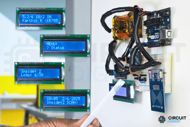
Keeping track of attendance should not feel like a daily hassle. Whether you are running a classroom, managing a small office, or organizing a community event, a simple, low-cost solution can go a long way. This RFID based attendance system using Arduino reads RFID cards to automatically log check-ins and check-outs, shows updates on an LCD, and stores attendance logs with real-time stamps using an RTC module. It's completely offline and stores data locally, so no need for an internet connection. The total cost is just around $30.

Why Choose Arduino for DIY RFID Attendance Tracker?

Arduino gives you full control over the system’s features without depending on expensive or limited commercial options. The MFRC522 RFID reader is accurate, and combining it with real-time clock and EEPROM modules means your data is both timestamped and safely stored, even during a power cut. Plus, once built, this setup is fully reusable and expandable for future upgrades like IoT integration or door control.

Key Features of RFID based attendance system

  • Automated RFID card scanning for both entry and exit
  • Real-time timestamp logging using DS1307 RTC
  • Local data storage with EEPROM, survives reboots
  • LCD display for live updates
  • Menu navigation via push buttons or serial monitor
  • Customizable card programming with personal data

Overview-Image-of-RFID-Based-Attendance-System-Using-Arduino

Components You’ll Need

  • Arduino Uno
  • MFRC522 RFID Reader
  • DS1307 RTC Module (with built-in AT24C32 EEPROM)
  • 16x2 I2C LCD Display
  • Push Buttons (x2)
  • RFID Cards/Tags
  • Breadboard, jumper wires, and 5V–12V power supply

RFID-Attendance-System-Using-Arduino
Real-World Applications

  • Classrooms – Track student attendance and prevent proxy entries
  • Offices – Log employee in/out times without manual input
  • Gyms & Clubs – Track member usage, ensure hygiene with contactless logging
  • Workshops – Monitor visitor entry or workshop sessions
  • Healthcare & Industry – Touchless logging for safety zones or shift tracking
This RFID based attendance system using Arduino is a great DIY project for anyone looking to solve a real problem while learning valuable electronics and programming skills. It’s affordable, fully offline, and scalable. Once set up, it can handle real-time check-ins, and you will know exactly how every part works.

Friday, 8 March 2024

How to Interface Ultrasonic Sensors with Arduino?


In this tutorial, we'll explore the process of connecting an
ultrasonic sensor to an Arduino board and displaying distance measurements on an LCD. Our goal is to provide a detailed understanding of the setup, operation, and coding involved in this project.

Components Required:


  • Arduino board (e.g., Arduino Uno)

  • HC-SR04 Ultrasonic Sensor

  • I2C LCD Display (e.g., 16x2 characters)

  • Jumper wires


Understanding the HC-SR04 Ultrasonic Sensor:


The HC-SR04 ultrasonic sensor has four pins:


  • VCC: Supply pin

  • GND: Ground pin

  • Trig: Trigger pin

  • Echo: Echo pin


Previous Projects:


We've employed the HC-SR04 with Arduino, Raspberry Pi, and PIC microcontroller in various projects, including:


Distance measurement with Arduino

Interfacing HC-SR04 with PIC microcontroller

Raspberry Pi obstacle-avoiding robot

IoT dumpster monitoring with Arduino & ESP8266


Working Principle:


The ultrasonic sensor emits high-frequency sound waves and detects their reflections. It comprises a transducer, which emits and receives ultrasonic waves, and signal processing circuitry to measure the time taken for the waves to travel and return.


Circuit Connection:


Connect the ultrasonic sensor's trig and echo pins to Arduino pins 4 and 5, respectively. This configuration enables the Arduino to trigger the sensor and measure the time taken for the echo pulse to return.


Arduino Code for Ultrasonic Sensor:


The Arduino code initializes serial communication and sets up the trigger and echo pins. It triggers the sensor, measures the duration of the echo pulse, and calculates the distance based on the speed of sound. The distance measurement is displayed on the Serial Monitor.


Adding an LCD Display:


Enhance the project by connecting an I2C LCD display to the Arduino. Use the SDA and SCL pins (A4 and A5 for Arduino Uno) for communication, along with VCC and GND. The LCD will provide real-time distance measurements alongside the serial output.


Practical Applications:


Explore various projects utilizing ultrasonic sensors, such as:


Interfacing with Raspberry Pi Pico for distance measurement

Building a smart blind stick for visually impaired individuals

Implementing an IoT-based smart dustbin management system using NodeMCU


This comprehensive guide offers detailed insights into interfacing an ultrasonic sensor with an Arduino and displaying distance measurements on an LCD. By following the steps outlined here, you can gain a better understanding of ultrasonic sensor operation and embark on exciting projects leveraging this technology.


For a complete tutorial, visit: https://youtu.be/bOZ5QdASm30