Friday 17 May 2024

Design Tips and Troubleshooting Guide for MCP2200 Protocol Converter

 The MCP2200, developed by Microchip Technology, serves as a USB-to-UART serial converter, facilitating the conversion of USB connections to serial interfaces.


Design Considerations


  • Ensure proper connectivity and voltage levels between the MCP2200 and connected devices.

  • Strategic placement of the USB port close to the IC for efficient data transfer.

  • Direct routing of data lines and minimal use of vias to reduce signal interference.

  • Include filter capacitors and maintain tight component arrangement to optimize performance.


Troubleshooting Tips


  • Verify signal connections and check voltage compatibility to address communication failures.

  • Test functionality by matching serial settings with connected devices and performing a loopback test for data transmission.

  • Use alternative USB cables to rule out potential cable issues.


Microcontroller programming, debugging, industrial control systems, DIY electronics projects, legacy device support, automation, and robotics. Alternatives include CH340, MA112AS16, FT230x, CP2102, PL2303HX, CH9102, CH343, CH341, CP2110, and FT232.


Detailed mechanical drawings and dimensions aid in creating custom footprints for PCB or CAD modeling, ensuring accurate integration of the MCP2200 into electronic designs. For detailed technical specifications and mechanical drawings, refer to the MCP2200 datasheet available here.


Thursday 16 May 2024

Calculate the Free-Running Frequency of Astable Multivibrators


Astable multivibrators, a fundamental component in electronics, operate continuously without external triggering, making them essential for generating periodic signals in various electronic devices. This article explores the calculation of the free-running frequency of astable multivibrators, shedding light on their functionality, applications, and significance.


What is an Astable Multivibrator?


An astable multivibrator is an oscillator circuit that alternates between its two unstable states without external triggering. Unlike monostable and bistable multivibrators, astable circuits lack a stable state, earning them the moniker of "free-running oscillators." They find applications in generating clock pulses, timing circuits, and light flashers, among others.


How Astable Multivibrator Works


The operation of an astable multivibrator hinges on the charging and discharging cycles of capacitors within the circuit. Typically consisting of two amplifying elements in a feedback loop, such as transistors or operational amplifiers, the circuit's timing intervals are determined by the values of capacitors and resistors. This continuous switching between states produces a square wave output, essential for digital circuits.


Basic Astable Multivibrator Circuit


Constructed using transistors, resistors, and capacitors, a basic astable multivibrator circuit comprises two amplifiers arranged with regenerative feedback. The cycling between conducting and cut-off states of the amplifiers generates oscillations, with resistor-capacitor pairs determining timing intervals.


Calculating Free-Running Frequency


The free-running frequency, representing the oscillation rate of an astable multivibrator, is calculated using the formula: f = 1 / (1.38 * R * C), where R is resistance in ohms and C is capacitance in farads. For symmetrical output waveforms, where R2 = R3 and C1 = C2, the time period (T) simplifies to T = 1.38 * R * C. This frequency calculation enables designers to tailor multivibrator behavior to meet specific project requirements.


Applications and Importance


Astable multivibrators find widespread use in electronics, serving in pulse generation, timers, LED flashers, and alarm circuits. Their versatility and simplicity, coupled with the ability to adjust the free-running frequency by tweaking component values, make them indispensable in both amateur and professional electronic projects. The adaptability of astable multivibrators underscores their utility and relevance in modern electronics.


In conclusion, understanding the calculation of the free-running frequency of astable multivibrators provides valuable insights into their functionality and applications, empowering electronics enthusiasts and professionals alike to harness their potential in diverse projects.


Understanding the CH341: A Practical Guide to Design, Troubleshooting, and Applications

 The CH341 is a USB-to-serial UART converter chip designed by WCH (Nanjing QinHeng Corp), offering convenience and cost-effectiveness for embedded systems and microcontroller communication. It facilitates USB connectivity between circuits and computers, supporting USB 1.1 and USB 2.0 compatibility. With versatility in protocols like UART, I2C, SPI, and parallel interfaces, it's widely used for various applications.


Troubleshooting Tips for CH341


  • Ensure correct connections between the chip and other components.

  • Check compatibility of signal voltage levels with connected devices.

  • Verify integrity of the USB cable for data transmission reliability.

  • Utilize ready-made programmers for programming EEPROMs directly with CH341.


Design Considerations for PCB Layouts


  • Place decoupling capacitance near the chip pins to stabilize power supply.

  • Align D+ and D- data lines in parallel with adequate ground or copper pour.

  • Minimize signal lead lengths between XI and XO pins to reduce clock disturbances.

  • Optimize placement of USB port near the CH341 chip and route data lines efficiently.


Applications of CH341 span microcontroller programming, debugging, industrial control systems, DIY electronics projects, legacy device support, and various conversions like USB to RS485, RS232, and TTL serial port. Its footprint and dimensional information aid in creating custom footprints for PCB design and CAD modeling, ensuring optimal integration into systems. For detailed technical specifications and mechanical drawings, refer to the CH341 datasheet available here.


Wednesday 15 May 2024

RFID Chip Implants: How Do They Work? Are They Legal and Safe?

In recent times, the integration of technology into our daily lives has reached new heights, with innovations like RFID chip implants capturing the interest of enthusiasts worldwide. In this article, we delve into the practical aspects and considerations associated with this emerging trend.


Understanding RFID Chip Implants:

RFID (Radio Frequency Identification) technology is not unfamiliar to most of us, having encountered it in various applications such as access cards and security tags. The concept of RFID chip implants extends this technology into the realm of biometrics, allowing for seamless integration with our biological systems.


Practical Applications:

Individuals like Mithun Devaiah, an engineer from Bangalore, demonstrate the practical applications of Arduino and RFID technology. With chips embedded in their hands, they showcase how simple gestures can control everyday tasks, from starting vehicles to accessing secured premises.


Accessibility and Safety:

Obtaining an RFID chip implant has become increasingly accessible, with DIY kits readily available online. However, the ease of acquisition raises concerns regarding safety and ethical implications, particularly with self-administered procedures.


Expert Insights:

Dr. Vishal Mishra provides valuable insights into the medical considerations surrounding RFID chip implants. From MRI compatibility to removal procedures, Dr. Mishra emphasizes the importance of cautious evaluation before undergoing such interventions.


Security Concerns:

While RFID technology offers convenience, it also introduces security vulnerabilities. Despite assurances of unique identifiers and limited range, concerns about hacking persist, prompting the need for robust security measures.


The decision to pursue an RFID chip implant is a personal one, requiring careful consideration of both the benefits and risks involved. As we navigate this evolving landscape of innovation, let us engage in informed discussions and prioritize safety and ethical considerations. Feel free to watch our accompanying YouTube video (RFID Chip Implant), where we discussed deeper into this emerging technology.


Tuesday 14 May 2024

Exploring the CH9102 USB to Serial Converter: Design and Troubleshooting

 The CH9102 stands out as a robust USB to serial UART converter, engineered by WCH (Nanjing QinHeng Corp), widely adopted in USB-to-serial adapter cables and development boards. This article delves into its design aspects and offers troubleshooting insights for smoother integration into projects.


Troubleshooting Tips:


  • Verify Connections: Double-check all connections to ensure they are properly made between the CH9102 and other components of the circuit.

  • Check Signal Voltage Compatibility: Ensure that the voltage levels of the signals (TX, RX, etc.) are compatible with the devices you are connecting to.

  • Test Serial Settings: Align serial settings, such as baud rate, between your computer and the device you are communicating with to ensure compatibility.

  • Conduct Loopback Test: Perform a loopback test by connecting the TX and RX pins of the CH9102. Send data from your computer, and if it is received correctly, it indicates that the CH9102 is functioning properly.

  • Address Computer Recognition Issues: Install correct drivers for the CH9102 chip on your computer. Check for hardware connection problems in the Device Manager, ensuring the chip is recognized without any error messages.


Design Considerations:


  • Strategic USB Port Placement: Place the USB port near the CH9102 IC on the PCB layout to minimize signal interference and optimize data transfer.

  • Direct Routing of Data Lines: Route data lines directly to reduce signal degradation and improve overall signal integrity.

  • Minimal Via Count: Minimize the number of vias in data lines to avoid signal loss and maintain signal integrity.

  • Inclusion of Filter Capacitors: Incorporate filter capacitors to stabilize voltage and reduce noise, enhancing the performance of the CH9102 and surrounding components.

  • Comprehensive Component Arrangement: Arrange components strategically to optimize space utilization and ensure efficient heat dissipation, contributing to the stability and reliability of the overall system.


Applications:

The CH9102 finds versatile applications in microcontroller programming, industrial control systems, DIY electronics projects, and legacy device support. Its adaptability extends to USB to RS485, RS232, and TTL serial port conversions, making it indispensable across various domains. 

Alternatives to CH9102 include CP2102, CP2104, CH340, MA112AS16, FT230x, PL2303HX, CH341, CH343, MCP2200, CP2110, and FT232.


As a cornerstone in USB connectivity solutions, the CH9102 offers reliability and efficiency. Understanding its design intricacies and troubleshooting methods ensures optimal performance in diverse project scenarios, making it a preferred choice for engineers and enthusiasts alike. For detailed technical specifications and mechanical drawings, refer to the CH9102 datasheet available here.


Sunday 12 May 2024

Advanced Arduino Project Exploration for Engineering Students

Are you an engineering student keen on practical electronics and embedded systems? Let's delve into a range of fascinating Arduino projects that will boost your skills and understanding of microcontroller applications.


1. DIY Arduino Bluetooth Car Controlled by Mobile Application

Have you ever wanted to create your own remote-controlled robot car? This project will teach you how to build a Bluetooth-controlled car that you can maneuver wirelessly using a mobile app. It's a fantastic gateway into the world of remote-controlled robotics and IoT.


2. Interfacing Seven Segment Display with Arduino

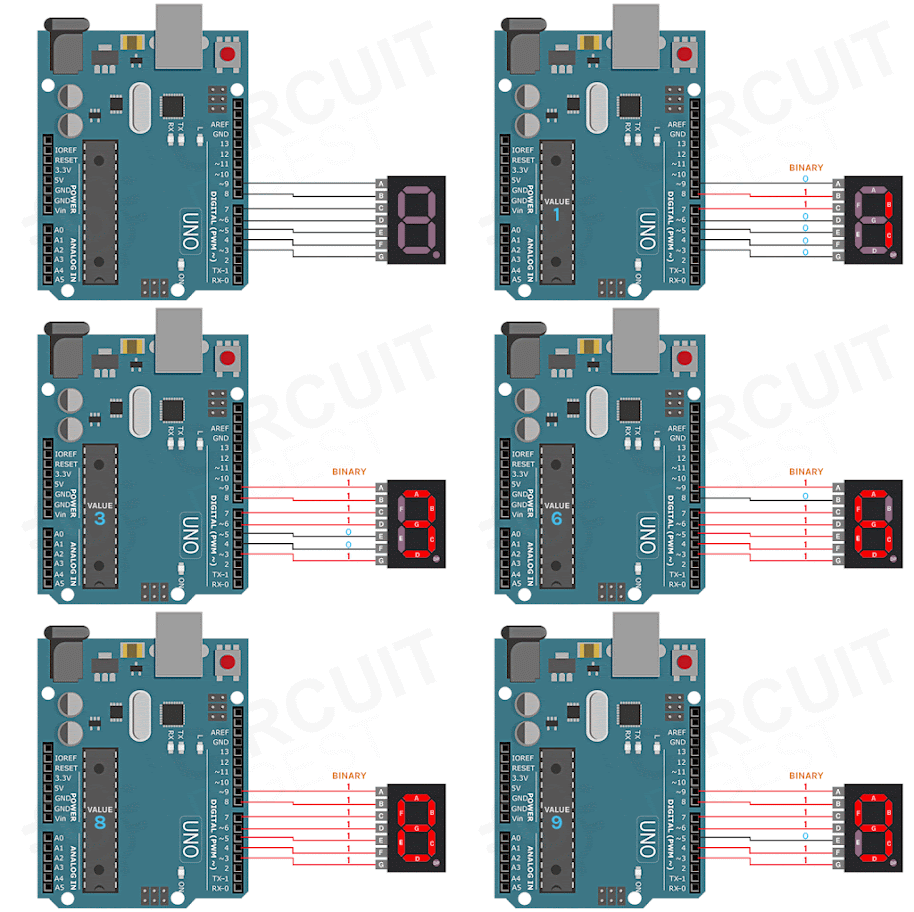
If you're new to electronics, learning how to connect and control a seven-segment display with Arduino is a great starting point. This project lays the foundation for understanding basic electronics and display technologies, which are useful in a wide range of digital applications.


3. Building your own Sun Tracking Solar Panel using an Arduino

Imagine a solar panel that automatically adjusts its position to maximize sunlight exposure throughout the day. With Arduino, you can create your own sun-tracking system that optimizes solar energy efficiency. It's a fascinating project for renewable energy enthusiasts.


4. Programming ESP32 using Arduino Labs for MicroPython

Looking to delve into MicroPython programming with the powerful ESP32 microcontroller? This project combines the versatility of ESP32 with the simplicity of MicroPython, making it ideal for various IoT and wireless communication applications.


5. Arduino-based Hourglass using Accelerometer and LED Matrix Displays

Transform the concept of a traditional hourglass into a modern marvel using Arduino, accelerometer sensors, and LED matrix displays. This unique project showcases the creative integration of sensors and visual displays in timekeeping devices.


6. DIY Motorized Solder Paste Dispenser for Automatic Solder Paste Application

Streamline your soldering tasks with a DIY motorized solder paste dispenser powered by an ATmega328 microcontroller. This project is essential for electronics enthusiasts engaged in manufacturing and prototyping.


7. Build a Battery Internal Resistance Meter with Arduino and Atmel ATtiny85 IC

Ensure optimal performance and longevity of batteries with a homemade internal resistance meter using Arduino and Atmel ATtiny85 IC. It's a handy tool for testing and maintaining batteries in portable electronic devices.


8. DIY Digital Distance Measuring Wheel using Rotary Encoder

Create your own digital distance measuring wheel using Arduino and a rotary encoder. This project is perfect for applications requiring precise distance measurements in robotics, surveying, or DIY projects.


9. Laser Engraving with DIY Arduino SCARA Robot

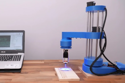
Explore the art of laser engraving by building a SCARA (Selective Compliance Assembly Robot Arm) robot powered by Arduino. This project merges precision robotics with laser technology, offering advanced prototyping possibilities.


10. Earthquake Indicator Using Arduino

Develop an earthquake indicator system using Arduino for real-time monitoring and detection of seismic activities. This project is invaluable for disaster preparedness and showcases Arduino's versatility in sensor applications.


These Arduino projects offer a comprehensive exploration of electronics, robotics, and IoT applications. Whether you're a beginner or an experienced engineer, each project provides valuable hands-on experience and opens doors to endless possibilities in the world of embedded systems and automation.


Get ready to unleash your creativity and engineering skills with these fascinating Arduino projects!


Friday 10 May 2024

L9110 Motor Driver IC: Design and Troubleshooting Tips

 The L9110 motor driver IC is a cost-effective solution for controlling DC motors in a variety of applications. With its wide input voltage range and bi-directional control capability, it offers versatility and simplicity for hobbyists and engineers alike.


Features of L9110


Low Quiescent Current: Operates efficiently with minimal power consumption.

Wide Supply Voltage Range: Compatible with voltages ranging from 2.5V to 12V.

High Current Output: Capable of delivering up to 800mA continuous current per channel.

TTL/CMOS Compatibility: Easily integrates with digital logic circuits for seamless control.

Built-in Clamp Diodes: Protects against reverse inductive load current for enhanced safety.


Applications of L9110: Robotics, printers, toys, DIY projects.

Alternatives to L9110: L293D, L298, TB6612FNG, DRV8833, MAX1508, TA6586,  DRV8871,MX1919.


Troubleshooting Tips


Circuit Resets: Ensure motor supply voltage is within the rated range and consider adding a capacitor parallel to the motor to mitigate voltage spikes.

Overheating IC: Address issues such as overloading, voltage spikes, or poor heat dissipation by adding capacitors to suppress spikes and ensuring proper ventilation.


Design Considerations


Proper Grounding: Establish a solid ground plane to minimize noise and interference.

Current Capacity: Ensure sufficient track width to handle high currents.

Decoupling Capacitors: Place capacitors close to power pins for efficient noise suppression.

Signal Tracks: Keep signal tracks short and direct for optimal performance.


The L9110 motor driver IC offers a simple and effective solution for controlling DC motors in various applications. With its compact size, versatile features, and ease of use, it's an excellent choice for hobbyists and professionals seeking reliable motor control. For detailed technical specifications and mechanical drawings, refer to the L9110 datasheet available here.


Thursday 9 May 2024

"How to Create Animated Eyes Using Arduino and OLED Displays?


Are you interested in making your own robots come to life with expressive eye animations? If you've been scouring the internet for ways to do this using Arduino and OLED displays but feel overwhelmed by all the information out there, don't worry! We've got you covered with a simple guide (
Arduino OLED Eyes)  to get you started.


What You'll Need


To begin, gather these basic components:


  • Arduino UNO

  • OLED Display (the small, square kind)

  • Breadboard

  • Jumper Wires (the male-to-male kind)

  • USB Cable for Programming


Setting Up the Circuit

First things first, let's connect the OLED display to the Arduino UNO. We'll use a special way of talking between them called the I2C protocol. This just means we'll connect some wires between the Arduino and the display. Also, remember that the OLED display with Arduino needs a special amount of power, so we'll connect it to a specific spot on the Arduino.


Exploring Different Eye Animations

Now comes the fun part – making the eyes move! We've found five different ways people have done this, and each has its own special features.


Option 1: Eye Animation by Intellar

Introducing a repertoire of eye expressions including Normal, Sleep, and Smile, Intellar's approach emphasizes simplicity and ease of use. With functions for adjusting eye position and size, it's ideal for projects requiring basic yet effective animations.


Option 2: Animated Eye by SpiderMaf

SpiderMaf's creation adds a human touch with customizable eye size and position. Compact and efficient, this method employs circles and pupils for precise eye movements, catering to projects seeking a more lifelike appearance.


Option 3: Akno by AbdulsalamAbbod

AbdulsalamAbbod's Akno offers a wide range of expressions, making it perfect for robotic projects. While lacking human-like characteristics, its versatility across various display types makes it a lightweight yet functional choice for hobbyist robots.


Option 4: OLED Moving Eyes by Vinny

Vinny's approach utilizes bitmap images for eye animations, enabling limitless customization. While offering extensive expression sets, memory consumption poses a challenge, restricting its compatibility with Arduino UNO due to space constraints.


Option 5: Robotic Eye Animations by Picaio

Picaio's method stands out with realistic eye movements and a diverse range of expressions. By optimizing bitmap usage, it achieves versatility without compromising on memory. Although slightly complex, it caters to projects demanding nuanced animations.


Now that you know the basics of creating animated eyes with Arduino and OLED displays, it's time to start experimenting! Whether you're building a simple robot or a complex machine, adding expressive eyes will bring your creation to life. So, grab your Arduino and get ready to make some eyes that sparkle with personality!