Wednesday 27 March 2024

Building a POV Display: Showing Images and Animations with LEDs and ESP32


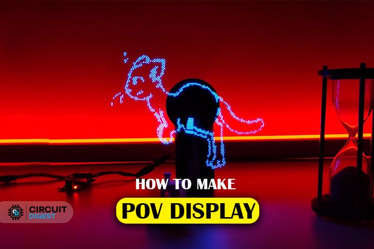
The Persistence of Vision (POV) Display project is about creating a visual illusion using LEDs mounted on rotating arms. This illusion tricks our eyes into seeing continuous motion, similar to how frames in a movie create the impression of movement.


We chose the ESP32 module as the brain of our display because it's affordable, easy to find, and powerful enough to handle the task. Each rotating arm has 64 LEDs, giving us a total display resolution of 128 pixels. This resolution strikes a good balance between image quality and simplicity.


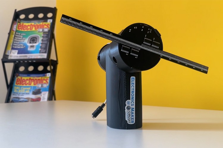
The circuitry controls how the LEDs light up as the arms rotate. We use components like shift registers, voltage regulators, and Hall effect sensors to manage power, LED activation, and synchronization with the rotation speed. Custom PCBs help organize and connect all the components neatly. Working with Viasion Technology, a reliable PCB manufacturer, ensures that our boards are of high quality and meet our project's needs.


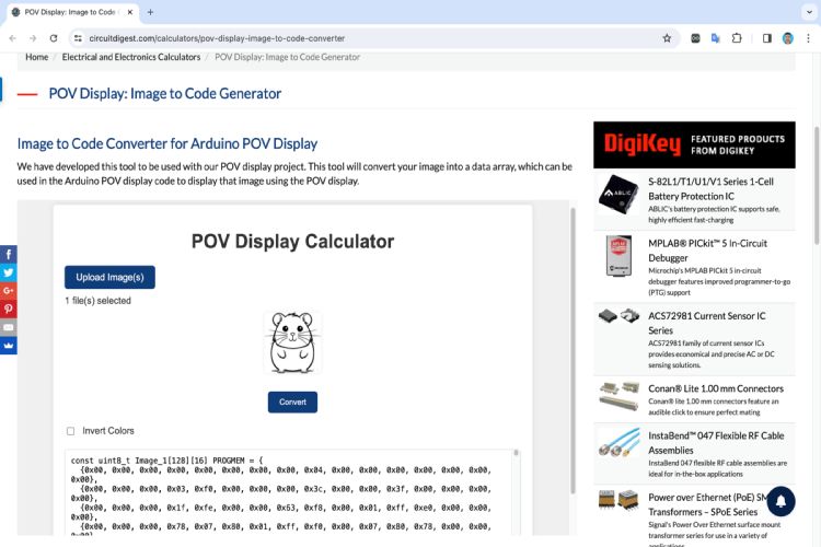
Converting images (image converter tool) for display involves transforming them into a format suitable for the rotating motion. This optimization improves storage efficiency and refresh rates, resulting in smoother animations. Our Arduino code controls everything, from animations to image rendering. It ensures that the LEDs light up at the right times to create captivating visuals. By using interrupts and careful calculations, the code syncs perfectly with the display's rotation.


Overall, our POV Display project is a fun exploration of visual illusions and technology. By following our detailed instructions and using the provided resources, anyone can build their own POV display and enjoy the magic of motion.


SGM2019 Series: Versatile Low-Power Linear Voltage Regulators


The SGM019 series by SGMicro presents a line of low-power, low-noise, and low-dropout CMOS linear voltage regulators, catering to diverse voltage requirements with nine fixed voltage outputs ranging from 1.2V to 3.3V, alongside an adjustable variant spanning 1.2V to 5.0V. Offering an ideal solution for battery-powered systems, these regulators boast very low quiescent and shutdown currents, enabling efficient power management. With a maximum output current of 300mA and an impressively low dropout voltage of 270mV, they facilitate reliable performance even in demanding applications such as RF systems, thanks to their ultra-low output noise and high PSRR.


Pinout Configuration and Identification:

The pinout configuration of the SGM2019 includes inputs for regulator input, ground, shutdown, reference-noise bypass, and output, with the adjustable voltage version featuring an additional pin for setting the output voltage. Identification of the variant is facilitated by specific markings on the device.


Key Features and Specifications:

Key features encompass a wide operating input voltage range, precise output voltage regulation, thermal shutdown protection, and output current limit. Available in compact SC70-5 and SOT-23-5 packages, they offer flexibility and ease of integration into various electronic designs.


Equivalents and Alternatives:

Equivalents and alternatives to the SGM2019 include AP2112, LD2985, TPS73633, TLV713, LP2985, AMS1117, MIC5225, MIC5205, and RT9193, providing options for different design requirements.


 Application Circuit and Use Cases:

The application circuit demonstrates simplicity, requiring minimal components for input and output filtering, with additional provisions for noise reduction in the form of bypass capacitors. Typical applications range from cellular telephones to handheld instruments, offering versatility across a spectrum of portable and battery-powered devices.


Detailed technical specifications and application guidelines can be referenced from the SGM2019 datasheet, facilitating seamless integration into electronic designs. Additionally, 2D CAD drawings provide dimensional insights for custom footprint creation and PCB or CAD modeling.


Thursday 21 March 2024

Types of Soldering Iron Tips and Their Uses

Soldering involves intricate work, and selecting the right soldering iron tip is crucial for quality results. Here's an overview of commonly available soldering iron tips and where they're best applied:

  1. Conical Tips: These have a pointed, tapered shape, perfect for precision work like soldering small components or surface mount devices (SMDs). They provide focused heat transfer for intricate tasks.
  2. Beveled Tips: Similar to conical tips but with flattened ends resembling a chisel. They hold more solder, making them versatile for various soldering projects, from fine work to tasks needing more heat.
  3. Chisel Tips: Featuring a flat surface, chisel tips offer a larger contact area for efficient heat transfer. They're great for soldering larger components, wires, or pads that require significant heat application.


Other Specialized Tips:


Knife Tip: Specifically, for drag soldering, where the pre-tinned tip is dragged across small SMD pads for simultaneous soldering.

Bent Tip: Useful for soldering hard-to-reach joints or in niche applications where standard tips may not be suitable.


Choosing the appropriate soldering iron tip is vital for precise and efficient soldering. Whether you're working on delicate components or larger joints, understanding these different tip types and their uses helps you tackle soldering tasks effectively.


Discover How to Choose Right Solders and Understand Different Types of it!


Soldering might seem like a small detail, but trust me, it makes a big difference in the quality of your circuit boards. However, selecting the right solder is often overlooked, despite its impact on solder joints' quality and reliability. In this article, we'll explore the various types of solder, their compositions, and applications to provide you with a comprehensive understanding.


Types of Solder and Their Composition


Solder is a fusible alloy with a low melting point used to bond metals in circuit boards. It primarily consists of tin, lead, and flux. Based on their composition, solder can be classified as:


1. Lead-free Solder


Lead-free solder, as the name suggests, is free of lead and typically comprises tin alloyed with metals like silver and copper. These solders comply with RoHS standards and are environmentally friendly. Common lead-free solder alloys include SAC305, SAC387, and SAC405, each with varying compositions and melting points.


2. Lead-based Solder


Leaded solder is the most common type and contains lead. It offers good wetting and mechanical properties, making it preferred for many applications. Common types of lead-based solder include 60/40, 63/37, and 50/50, each with specific melting points and characteristics.


Important Considerations When Choosing Solder:


Usability: Lead-free solder tends to be harder to work with due to its higher melting point.

Flux Properties: Fluxes used with lead-free solder are typically more corrosive and require careful handling.

Health Hazards: Elevated temperatures required for lead-free soldering can pose health risks due to increased flux and metal vapor production.

Whisker Formation: Solder alloys containing mainly tin can develop whiskers over time, potentially causing short circuits.

Flow Characteristics: Lead-free solder is less free flowing compared to leaded solder, which may affect soldering ease.

Types of Solder Based on Core Material


Solder wire can have different core materials, each serving specific purposes:


Uncored Solder: Plain solder without a flux or rosin core, often requiring pre-fluxing for application.

Rosin-cored: Contains rosin flux, which leaves residue requiring cleanup.

Flux-cored: Contains flux to aid soldering but may require cleanup due to its acidic nature.

Acid core solder: Features acid-based flux, primarily used in plumbing to prevent oxide layer formation.


Choosing the right solder is crucial for successful soldering projects. While leaded solder may be more convenient for hobbyists, lead-free solder offers environmental benefits and compliance with regulations. Additionally, opting for flux-cored solder enhances soldering ease and efficiency. Understanding the different types of solder and their applications empowers individuals to make informed choices for their soldering needs.

Friday 8 March 2024

Understand the Basics and Applications of NPN & PNP Transistors


Transistors represent a pivotal invention in electronics, revolutionizing the industry with their versatility and complexity. Among the various types, Bipolar Junction Transistors (BJTs) remain widely popular, especially the NPN and PNP variants. Let's delve into the fundamentals of BJTs and explore the distinctions between NPN and PNP transistors.


NPN vs PNP: The Basics


Both NPN and PNP transistors operate on the same underlying principle but differ in their basing and power supply polarity. In an NPN transistor, a positive voltage applied to the base relative to the emitter allows current flow from the collector to the emitter. Conversely, in a PNP transistor, a negative voltage at the base enables current flow from the emitter to the collector.


Understanding the Construction


NPN transistors feature a P-type material sandwiched between two N-type materials, while PNP transistors have an N-type material between two P-type materials. Due to the differing charge carriers (electrons in NPN and holes in PNP), NPN transistors typically exhibit faster recovery times and higher switching speeds.


Identifying and Testing


Identifying NPN and PNP transistors can be done using a multimeter's diode test mode. For NPN, a voltage drop occurs with the red probe on the base and black probe on the emitter. In contrast, for PNP, the voltage drop is observed with the black probe on the base and red probe on the emitter. Testing involves checking the forward-biased base-emitter junction for voltage drops.


Differences and Applications


NPN transistors are favored in applications requiring a common ground reference, thanks to their simplified circuit design. Additionally, they offer higher electron mobility and compatibility with N-channel MOSFETs. In contrast, PNP transistors find utility in specific scenarios, often in complementary configurations with NPN transistors.


Popular Options


Some widely used NPN transistors include 2N2222, BC547, and BC337, while popular PNP variants include 2N2907 and BC557. These transistors cater to a range of applications, from amplification to switching circuits.


Conclusion


Understanding the nuances between NPN and PNP transistors is crucial for designing effective electronic circuits. By grasping their principles and applications, engineers and enthusiasts can harness the full potential of these essential components in their projects.


How to Interface Ultrasonic Sensors with Arduino?


In this tutorial, we'll explore the process of connecting an
ultrasonic sensor to an Arduino board and displaying distance measurements on an LCD. Our goal is to provide a detailed understanding of the setup, operation, and coding involved in this project.

Components Required:


  • Arduino board (e.g., Arduino Uno)

  • HC-SR04 Ultrasonic Sensor

  • I2C LCD Display (e.g., 16x2 characters)

  • Jumper wires


Understanding the HC-SR04 Ultrasonic Sensor:


The HC-SR04 ultrasonic sensor has four pins:


  • VCC: Supply pin

  • GND: Ground pin

  • Trig: Trigger pin

  • Echo: Echo pin


Previous Projects:


We've employed the HC-SR04 with Arduino, Raspberry Pi, and PIC microcontroller in various projects, including:


Distance measurement with Arduino

Interfacing HC-SR04 with PIC microcontroller

Raspberry Pi obstacle-avoiding robot

IoT dumpster monitoring with Arduino & ESP8266


Working Principle:


The ultrasonic sensor emits high-frequency sound waves and detects their reflections. It comprises a transducer, which emits and receives ultrasonic waves, and signal processing circuitry to measure the time taken for the waves to travel and return.


Circuit Connection:


Connect the ultrasonic sensor's trig and echo pins to Arduino pins 4 and 5, respectively. This configuration enables the Arduino to trigger the sensor and measure the time taken for the echo pulse to return.


Arduino Code for Ultrasonic Sensor:


The Arduino code initializes serial communication and sets up the trigger and echo pins. It triggers the sensor, measures the duration of the echo pulse, and calculates the distance based on the speed of sound. The distance measurement is displayed on the Serial Monitor.


Adding an LCD Display:


Enhance the project by connecting an I2C LCD display to the Arduino. Use the SDA and SCL pins (A4 and A5 for Arduino Uno) for communication, along with VCC and GND. The LCD will provide real-time distance measurements alongside the serial output.


Practical Applications:


Explore various projects utilizing ultrasonic sensors, such as:


Interfacing with Raspberry Pi Pico for distance measurement

Building a smart blind stick for visually impaired individuals

Implementing an IoT-based smart dustbin management system using NodeMCU


This comprehensive guide offers detailed insights into interfacing an ultrasonic sensor with an Arduino and displaying distance measurements on an LCD. By following the steps outlined here, you can gain a better understanding of ultrasonic sensor operation and embark on exciting projects leveraging this technology.


For a complete tutorial, visit: https://youtu.be/bOZ5QdASm30


Thursday 7 March 2024

Understand How to use Seven Segment Display with Arduino


Visual indication is crucial in modern electronics, enhancing user interaction. The Seven-Segment Display has been a reliable solution for decades, widely used across industries for numeric value display. It offers practicality, cost-effectiveness, and readability in various conditions, making it suitable for applications like counters and token systems.

Seven Segment Display:


Displayed in a simulation where an Arduino counts from 0 to 9, these displays come in various sizes, commonly 0.56 inches. Comprising seven LEDs arranged to form digits with an additional LED for the decimal point, they offer flexibility in showcasing numbers from 0 to 9.


Types of seven segment display:


Segment Displays are classified as Common Cathode (CC) and Common Anode (CA) based on LED pin connections.


  • Common Cathode Displays: Cathodes of LEDs connect to the common pin, linked to the ground, activated by a high pulse.

  • Common Anode Displays: Anodes connect to the common pin, linked to the positive rail, activated by a low pulse.


Both types illuminate specific segments to display numbers or characters.


Displaying Number:


Activation of corresponding pins with the appropriate signal displays numbers or patterns. For Common Cathode, a Logic 0 is used, and for Common Anode, a Logic 1. Alphabets can also be displayed.


Tinkercad simulation demonstrates interfacing with Arduino, displaying numbers 0 to 9.


Connecting a Seven Segment Display with Arduino:


Place the display module on a breadboard, connecting the common pin to ground. Wire other pins to digital pins D2 to D9 through current limiting resistors.


Arduino Code:

Install the SevSeg library via Arduino IDE's Library Manager. Copy provided code, counting from 0 to 9, displaying on the display.


Projects Featuring Seven Segment Displays:


  1. Guide and code for connecting Seven Segment Display to Raspberry Pi.

  2. Build a digital clock using Arduino and four 7-segment displays.

  3. Create a digital counter with 555 Timer IC.


Seven segment displays offer a straightforward method for numeric display tasks, with applications extending from Arduino to Raspberry Pi, facilitating practical electronics projects.


Wednesday 6 March 2024

All About Sensors: Understanding Their Function and Sensing Capabilities

Sensors are vital components in our modern world, enabling us to perceive and interact with our environment in various ways. They come in different types, each with unique applications and functionalities. In this article, we'll explore the basics of sensors and its types, applications, and operational principles.


What are Sensors?


Sensors are devices designed to detect changes in their environment and provide output signals, either analog or digital. These signals serve various purposes, from displaying information to controlling processes in closed-loop systems. Essentially, sensors act as our technological senses, allowing devices to detect and respond to changes in their surroundings accurately.


Differentiating Sensors and Transducers


It's essential to distinguish between sensors and transducers. Sensors detect environmental changes and provide feedback, while transducers convert physical quantities into electrical signals or vice versa. Sensors require external power, whereas transducers can operate independently. Understanding this difference is crucial for grasping the functionality of different sensor types.


Classification of Sensors


Sensors can be classified in various ways, including active vs. passive and analog vs. digital. Active sensors, like piezoelectric sensors, don't need external power sources, while passive sensors, such as thermistors, do. Analog sensors produce continuous signals, while digital sensors generate discrete values.


Common Types of Sensors and Their Applications


Temperature Sensor: Measures thermal energy accurately, vital in industrial, automotive, medical, and environmental monitoring.


Position Sensors: Determine object positions, essential for robotics, motion systems, and automotive applications.


Ultrasonic Sensors: Utilize ultrasonic waves for distance measurement and object detection, widely used in robotics and industrial automation.


Proximity Sensor: Detects nearby objects without contact, crucial for automotive, industrial automation, and safety systems.


Hall Effect Sensors: Detect external magnetic fields, finding applications in position detection and automotive systems.


Light Sensors: Convert light energy into electrical signals, used in ambient light detection, object detection, and photography.


Gas and Chemical Sensors: Detects presence and concentration of gases, essential for safety systems, environmental monitoring, and industrial processes.


Humidity Sensors: Measure humidity levels in the air, employed in HVAC systems, weather stations, and agriculture.


Radiation Detectors: Detects various types of radiation, crucial for nuclear power plants, medical imaging, and radiation safety.


Sensors are fundamental components of modern technology, facilitating our interaction with the environment in diverse ways. Understanding their types, applications, and operational principles is essential for effectively harnessing their capabilities. Whether monitoring temperature, detecting motion, or ensuring air quality, sensors play a pivotal role in shaping our world.