Showing posts with label OLED. Show all posts

Tuesday, 6 May 2025

PMW3901 Optical Flow Sensor with ESP32 – Position Hold for Drones

PMW3901 Optical Flow Sensor with ESP32

The PMW3901 is an optical flow sensor often used in drones and robotics to detect motion relative to the ground. It helps maintain a steady position, especially when GPS signals are weak or unavailable. This guide explains how the sensor works, its features, and how to use it with an ESP32. It also includes examples for visualizing motion on a web browser and an OLED display.

What is the PMW3901 Optical Flow Sensor?

The PMW3901 is a compact sensor that detects movement by tracking patterns in grayscale images. It does not provide absolute position data but measures how much and in what direction the surface underneath has shifted.

Common PMW3901 Modules

1. Pimoroni PMW3901 Pinout

Pimoroni-PMW3901-Sensor-Module-Pinout


2. Generic PMW3901 Module Pinout

PMW3901-Sensor-Pinout

Applications of the PMW3901 optical flow sensor with ESP32

  • Indoor Navigation
  • Position Holding in Drones
  • Autonomous Robots
  • Gesture Recognition Systems

The PMW3901 is a reliable optical flow sensor suitable for indoor drones and small robots. It provides real-time X/Y movement data, uses low power, and can be integrated with ESP32 using SPI. Visualization on a web interface or OLED display helps in testing and understanding motion detection.

For in-depth explanation and code : Interfacing PMW3901 Optical Flow Sensor With ESP32

https://circuitdigest.com 

Robotics Projects |Arduino Projects | Raspberry Pi Projects|

Thursday, 1 May 2025

How to use nRF24L01 module with Arduino


If you're looking to add wireless communication to your project, the Arduino and nRF24L01 module combo is one of the most reliable and cost-effective solutions available. Whether you're building a DIY spy bug, a long-range walkie-talkie, or just want to control devices wirelessly, the nRF24L01 lets you send and receive data over long distances using the 2.4GHz band. In this guide, you'll learn how to create your own wireless Arduino project using the nRF24L01 transceiver , complete with circuit diagrams and step-by-step instructions.


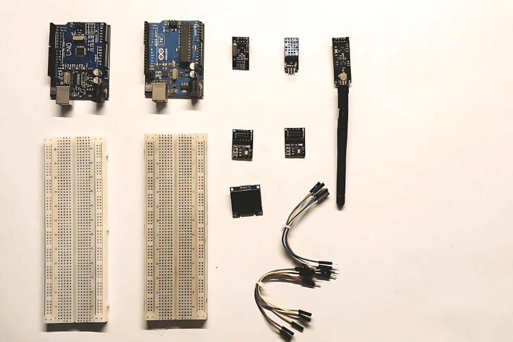
Components Required

  1. Arduino Uno – x2

  2. nRF24L01 – x2

  3. 3.3V Adapter Board for nRF24L01 – x2

  4. DHT11 Temperature and Humidity Sensor

  5. OLED Display

  6. Breadboard – x2

  7. Jumper Wires

Understanding the nRF24L01 Module

The nRF24L01 is a compact 2.4GHz transceiver module designed by Nordic Semiconductor. It supports both transmitting and receiving data and communicates with microcontrollers over the SPI interface. This module operates on 3.3V and consumes very little power—about 12mA during data transmission. There are multiple versions of this module, including one with an external antenna and an onboard PA (Power Amplifier) and LNA (Low-Noise Amplifier) chip (RFX2401C), which greatly improves the communication range and reliability, especially in noisy environments.

3.3V-Adapter-Board-for-nRF24L01

Final Working and Testing

Once Code uploaded:

  • The transmitter reads temperature and humidity every 2 seconds.
  • The receiver gets the data and displays it on the OLED and Serial Monitor.
  • You can test the range indoors or outdoors to explore its full potential.
Applications of nRF24L01
  • Home automation
  • Wireless sensors
  • Remote-controlled robots.
In-depth Code and Project Tutorial : Interfacing nRF24L01 with Arduino UNO

Thursday, 9 May 2024

"How to Create Animated Eyes Using Arduino and OLED Displays?


Are you interested in making your own robots come to life with expressive eye animations? If you've been scouring the internet for ways to do this using Arduino and OLED displays but feel overwhelmed by all the information out there, don't worry! We've got you covered with a simple guide (
Arduino OLED Eyes)  to get you started.


What You'll Need


To begin, gather these basic components:


  • Arduino UNO

  • OLED Display (the small, square kind)

  • Breadboard

  • Jumper Wires (the male-to-male kind)

  • USB Cable for Programming


Setting Up the Circuit

First things first, let's connect the OLED display to the Arduino UNO. We'll use a special way of talking between them called the I2C protocol. This just means we'll connect some wires between the Arduino and the display. Also, remember that the OLED display with Arduino needs a special amount of power, so we'll connect it to a specific spot on the Arduino.


Exploring Different Eye Animations

Now comes the fun part – making the eyes move! We've found five different ways people have done this, and each has its own special features.


Option 1: Eye Animation by Intellar

Introducing a repertoire of eye expressions including Normal, Sleep, and Smile, Intellar's approach emphasizes simplicity and ease of use. With functions for adjusting eye position and size, it's ideal for projects requiring basic yet effective animations.


Option 2: Animated Eye by SpiderMaf

SpiderMaf's creation adds a human touch with customizable eye size and position. Compact and efficient, this method employs circles and pupils for precise eye movements, catering to projects seeking a more lifelike appearance.


Option 3: Akno by AbdulsalamAbbod

AbdulsalamAbbod's Akno offers a wide range of expressions, making it perfect for robotic projects. While lacking human-like characteristics, its versatility across various display types makes it a lightweight yet functional choice for hobbyist robots.


Option 4: OLED Moving Eyes by Vinny

Vinny's approach utilizes bitmap images for eye animations, enabling limitless customization. While offering extensive expression sets, memory consumption poses a challenge, restricting its compatibility with Arduino UNO due to space constraints.


Option 5: Robotic Eye Animations by Picaio

Picaio's method stands out with realistic eye movements and a diverse range of expressions. By optimizing bitmap usage, it achieves versatility without compromising on memory. Although slightly complex, it caters to projects demanding nuanced animations.


Now that you know the basics of creating animated eyes with Arduino and OLED displays, it's time to start experimenting! Whether you're building a simple robot or a complex machine, adding expressive eyes will bring your creation to life. So, grab your Arduino and get ready to make some eyes that sparkle with personality!


Tuesday, 27 July 2021

DIY Portable Ultrasonic Digital Ruler using ATtiny85 Microcontroller


Distance measurement of an object in the path of the person, equipment, or a vehicle or moving object is used in a large number of applications such as robotic movement control, vehicle control, blind man’s walking stick, medical equipment, etc. There are many methods available for distance measurement but measurement using Ultrasonic sensor is one of the cheapest among other options. In this project, we are going to use HC-SR04 Ultrasonic Sensor with ATtiny85 microcontroller IC and OLED display module to build a digital ultrasonic ruler.


For the circuit diagram, code and gerber files, please visit the project page: DIY Digital Ruler


For more electronics project, visit: projects page


Monday, 10 December 2018

Interfacing OLED Display with Android Phone

connecting OLED display with Android Phone using bluetooth

Most of us would be familiar with the 16×2 Dot matrix LCD display that is used in many projects to display some information to the user. But these LCD displays have a lot of limitation in what they can do. In this tutorial, we will use OLED to display some basic information from the Android smartphone like Time, date, network strength and battery status. This project provides a basic idea and framework to build an Arduino based SmartWatch and can be further extended to display incoming calls, messages and many more on OLED display.

Here you can find the basic circuit diagram to interface the OLED with Android phone using a bluetooth module:

Circuit Diagram for Interfacing OLED display with Android Phone to build a Smart Watch

To check out the complete project with codes and required libraries for arduino, visit the link below: