Here are some interesting and easy arduino based projects:
1.
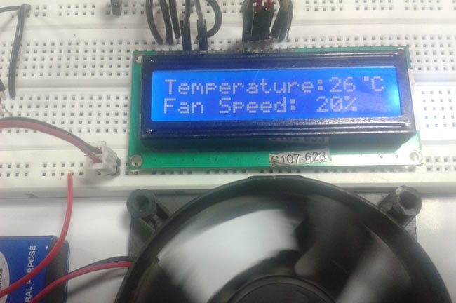
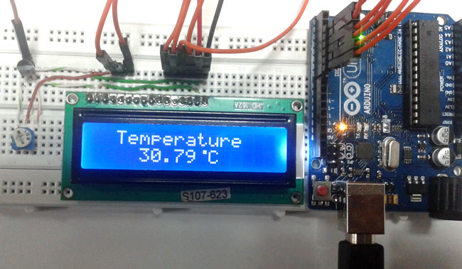
Digital Thermometer
Thermometers are useful apparatus being used since long time for temperature measurement. In this project we have made an Arduino based digital thermometer to display the current ambient temperature and temperature changes on a LCD unit in real time.
2.
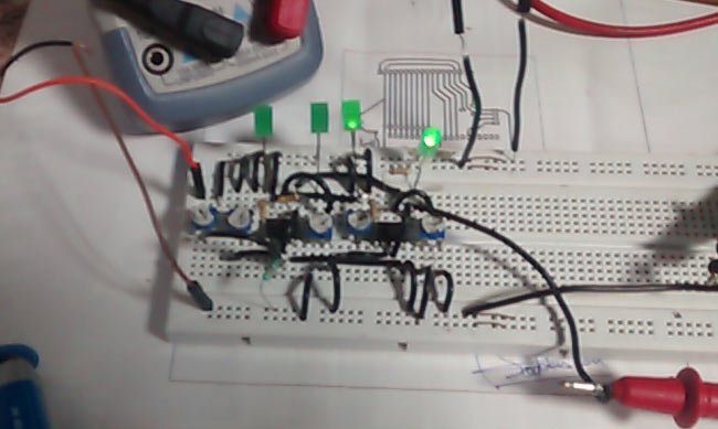
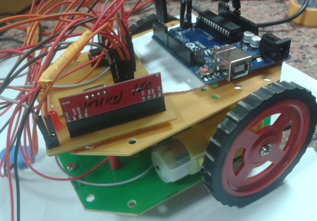
Line Follower Robot
Line follower Robot is a machine which follows a line, either a black line or white line. Basically there are two types of line follower robots: one is black line follower which follows black line and second is white line follower which follows white line. Line follower actually senses the line and run over it.
3.
Digital Alarm Clock
This Arduino based Real time clock is a digital clock to display real time using a RTC IC DS1307 which works on I2C protocol. Real time clock means it runs even after power failure. When power is reconnected, it displays the real time inrespective to the time and duration it was in off state.
4.
Digital Tachometer
Tachometer is a RPM counter which counts the no. of rotation per minute. There are two types of tachometer one mechanical and other one is digital. Here we are going to design an Arduino based digital tachometer using IR sensor module to detect object for count rotation of any rotating body.
5.
Distance Measurement
Ultrasonic sensors are great tools to measure distance without actual contact and used at several places like water level measurement, distance measurement etc. This is an efficient way to measure small distances precisely. In this project we have used an Ultrasonic Sensor to determine the distance of an obstacle from the sensor.
6.
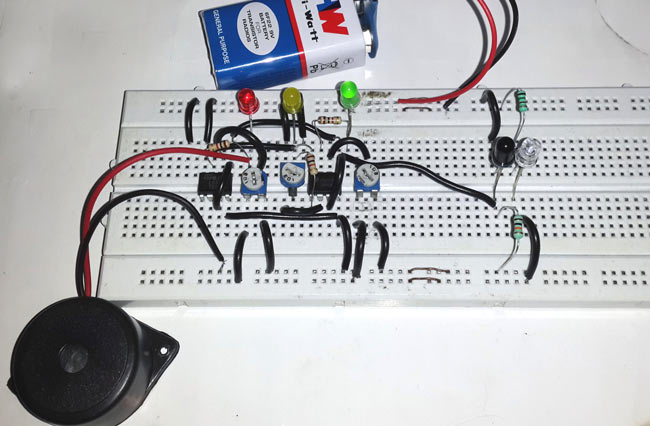
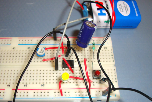
LPG Leakage Detector
While LPG is an essential need of every household, its leakage could lead to a disaster. To alert on LPG leakage and prevent any mishappening there are various products to detect the leakage. Here we have developed an Arduino based LPG gas detector alarm. If gas leakage occurs, this system detects it and makes an alert by buzing the buzzer attached with the circuit. This system is easy to build and anyone who have some knowledge of electronics and programing, can build it.
7.
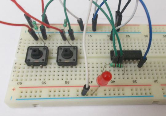
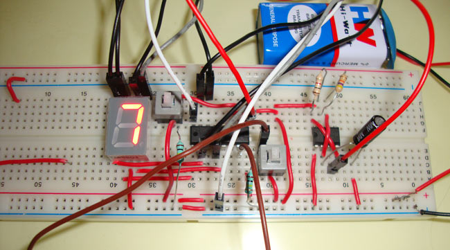
Digital Dice
We all are familiar with dice and often played LUDO or SANP SIDI (Snake & Ladders) game by using dice. Dice is a squire type solid box which contains 6 different numbers on all of its sides. We throw dice on a surface to get a random number while playing the games. In this project we have tried to replicate it with a digital dice using arduino uno board. In place of throwing the dice, here we need to press a button to get a random number between 0 to 6.
Hope you like the above projects. Find here more such arduino based projects here: http://circuitdigest.com/arduino-projects